S&C Instruction Sheet 766-510
11
Installation
CAUTION
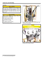
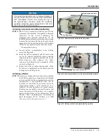
Make sure the lifting brackets are swung down into
their resting position. Leaving the lifting brackets in
the up/lifting position may cause flashover when the
IntelliRupter fault interrupter is energized.
(b) When all nuts and lag screws have been fully
tightened, remove the hoist from the lifting
brackets. Swing down the two lifting brackets.
Grounding the Base
DANGER
The IntelliRupter fault interrupter base must be
connected to a suitable earth ground at the base
of the utility pole before energizing, and at all
times when energized. The ground wire(s) must
be bonded to the system neutral, if present. If the
system neutral is not present, proper precautions
must be taken to ensure that the local earth ground
cannot be severed or removed.
Failure to observe
these instructions can result in serious personal
injury or death.
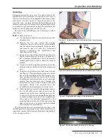
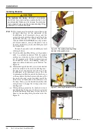
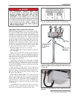
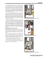
STEP 5.
Ground the IntelliRupter fault interrupter base
by solidly connecting one Number 2 AWG copper
wire (or two Number 6 AWG copper wires, or
wires having an equivalent cross-sectional area)
to the grounding lug on the back of the
IntelliRupter fault interrupter base. Connect the
other end of the wire(s) to a suitable earth ground
at the base of the utility pole, and bond them to
the system neutral, if present. If the system
neutral is not present, proper precautions must
be taken to ensure the local earth ground cannot
be severed or removed.
Ground impedance must be 25 ohms or less
to properly protect the equipment.
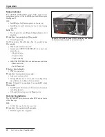
Installing Surge Arresters
NOTICE
Surge arresters are required on both sides of an
IntelliRupter fault interrupter to protect it from surges
beyond its ratings.
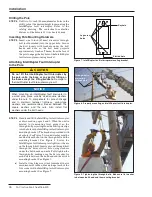
STEP 6.
See the Optional Features table in S&C
Specification Bulletin 766-31, “S&C
IntelliRupter® PulseCloser® Fault Interrupter,”
for a list of available surge arrester options.
Mounting provisions for surge arresters are
provided. If optional surge arresters have not
been specified, install surge arresters of the
desired voltage rating on both sides of the
IntelliRupter fault interrupter using hardware
supplied with the arresters. Ground surge
arresters to the IntelliRupter fault interrupter
base; a separate ground strap between poles is
not required. Refer to reference drawing RD-
6924 included in the detailed instruction
manual RD-6949.
Connectors, Terminal Pads, and Conductors
Note:
DO NOT wire-brush terminal pads. Wire brushing
may scratch the plating.
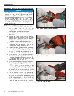
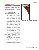
STEP 7.
Prepare the surfaces of connectors, terminal
pads, and conductors as follows:
CAUTION
Terminal pads are not intended for dead-ending
and should only have jumpers attached to them.
Mechanical loading from each jumper must not
exceed 90 lbs. in-line and 30 lbs. perpendicular to
the terminal pad. Refer to the latest issue of ANSI/
IEEE Standard C37.32, Section 8.8.2.2.
(a) Apply a liberal coating of “NO-OX-id E®”
(available from Sanchem Inc.) or other suitable
aluminum connector compound to the connector
surface.
(b) Securely bolt the connectors to the terminal
pads.
(c) Prepare the conductors using established
procedures, and clamp them in the connectors. If
the optional wildlife protection feature is
furnished (catalog number suffix “-W1” or “-W2”),
refer to the “Installing Optional Wildlife
Protection Feature” section on page 12.