S&C Instruction Sheet 766-510
21
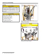
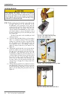
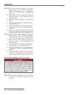
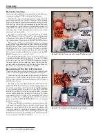
Figure 31. Disconnect open and tagged.
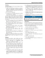
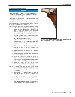
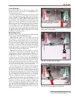
Figure 30. Opening the disconnect operating lever.
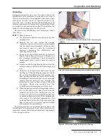
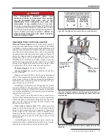
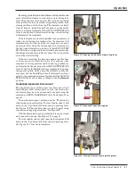
Figure 32. Closing the disconnect operating lever.
Operation
Enabling ground trip block will immediately disable and
reset all selected elements, even if they were timing for a
fault when the lever was moved. The ground trip block
lever is effective for any profile: all general profiles, both
closing profiles, and hot line tag. The elements available
for selection are: ground, negative sequence, and sensitive
earth overcurrent elements. If the GROUND TRIP BLOCK
lever is configured to block circuit testing, circuit testing
will immediately terminate.
If the test sequence was in the middle of an open interval
when circuit testing was terminated, the sequence will
immediately go to lockout. If the test sequence was not in
an open interval when the test sequence was terminated,
the next trip will result in a lockout. If the GROUND TRIP
BLOCK lever is configured for an alternate general profile,
the designated general profile becomes the active profile
unless the unit is testing.
If the unit is testing, the alternate general profile does
not become active until the active test sequence has
completed. Closing profiles and hot line tag profiles are
not affected by the position of the GROUND TRIP BLOCK
lever. SCADA or IntelliLink software commands to change
the general profile while using the alternate profile are
accepted, but the IntelliRupter fault interrupter will not
revert to the commanded general profile until the GROUND
TRIP BLOCK lever has been returned to the
Unblocked
position.
Hookstick-Operated Disconnect
The hookstick-operated disconnect on Disconnect Style
IntelliRupter fault interrupters can be operated after
the interrupters have been manually opened using the
interrupter OPEN/CLOSE/READY lever. See Figure 25 on
page 19.
To open the disconnect, pull down on the “
O”
position of
the disconnect operating lever. To close the disconnect, pull
down on the “
I”
position of the disconnect operating lever.
See Figure 30. The open disconnect can be “tagged” using
conventional tagging procedures. See Figure 31.
With the disconnect open, the interrupters can be closed
and opened for testing. See Figure 27 on page 19.
To close the disconnect, first open the interrupters. Pull
down on the “
I”
position of the disconnect operating lever.
See Figure 32. Close the interrupters.

