S&C Instruction Sheet 766-510
15
Installing SCADA Antenna
NOTICE
Make sure there is a clear line of sight to the antennas
of other IntelliRupter fault interrupters and/or other radio-
equipped automated distribution equipment.
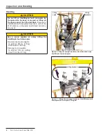
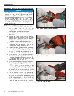
The antenna connector is located on the underside of the
IntelliRupter fault interrupter base.
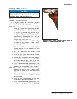
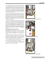
If a bracket-mounted antenna has not been specified,
screw the 5-dBi gain wire-whip antenna (if provided) into
the connector on the base. See Figure 19.
STEP 12.
Bracket-mounted antennas (catalog number
suffi x “-B1” through “-B3”) are shipped partially
assembled, with the bracket attached to the
base on the side opposite the interrupter
OPEN/CLOSE/READY lever. The bracket can be
mounted at whichever end of the base achieves
the highest-quality radio signal. Position 1 is the
end closest to the antenna connector. Position 2
is the end farthest from the antenna connector.
See Reference Drawing RD-6927.
To install the antenna bracket for catalog
number suffix “-B1” (900-MHz, 3-dBd gain, omni-
directional 25-inch fiberglass antenna) mounted
in position 1:
(a) Remove and retain the hardware attaching the
antenna bracket to the IntelliRupter fault
interrupter base.
(b) Rotate the bracket 180 degrees, as viewed from
the top.
(c) Attach the bracket to the base using the hardware
removed in Step 12 (a).
(d) Loosen the U-bolt that attaches the antenna to
the bracket. Reposition the antenna in the U-bolt
so it points up and the fi berglass section is above
the top of the bracket. Tighten the U-bolt.
(e) Attach the antenna cable, and secure it with
three plastic cable ties (provided) at the locations
marked on page 2 of Reference Drawing RD-6927.
STEP 13.
To install the antenna bracket for catalog
number suffi x “-B1” (900-MHz, 3-dBd gain, omni-
directional 25-inch fi berglass antenna) mounted
in position 2:
(a) Remove and retain the hardware attaching the
antenna bracket to the IntelliRupter fault
interrupter base.
(b) Attach the bracket to the opposite end of the base
using the hardware removed in Step 13 (a).
(c) Attach the antenna cable, and secure it with
three plastic cable ties (provided) at the locations
marked on page 2 of Reference Drawing RD-6927.
Installation
Figure 19. Wire-whip antenna attached to the connector on the
bottom of IntelliRupter fault interrupter base.

