20
S&C Instruction Sheet 766-510
Operation
Manual Hot Line Tag
A hot line tag can be set locally using the hookstick lever,
or remotely using SCADA or IntelliLink software.
The hot line tag is normally removed using the same
method by which it was applied. However, the hookstick
lever can be used to remove electronically set tags as well.
A hot line tag will only be cleared when all manually set and
electronically set tags have been cleared. This approach sat-
isfies NESC 442.E requirements, which allow local removal
of a remotely set hot line tag if local indication of the
electronic tag is provided.
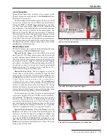
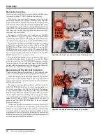
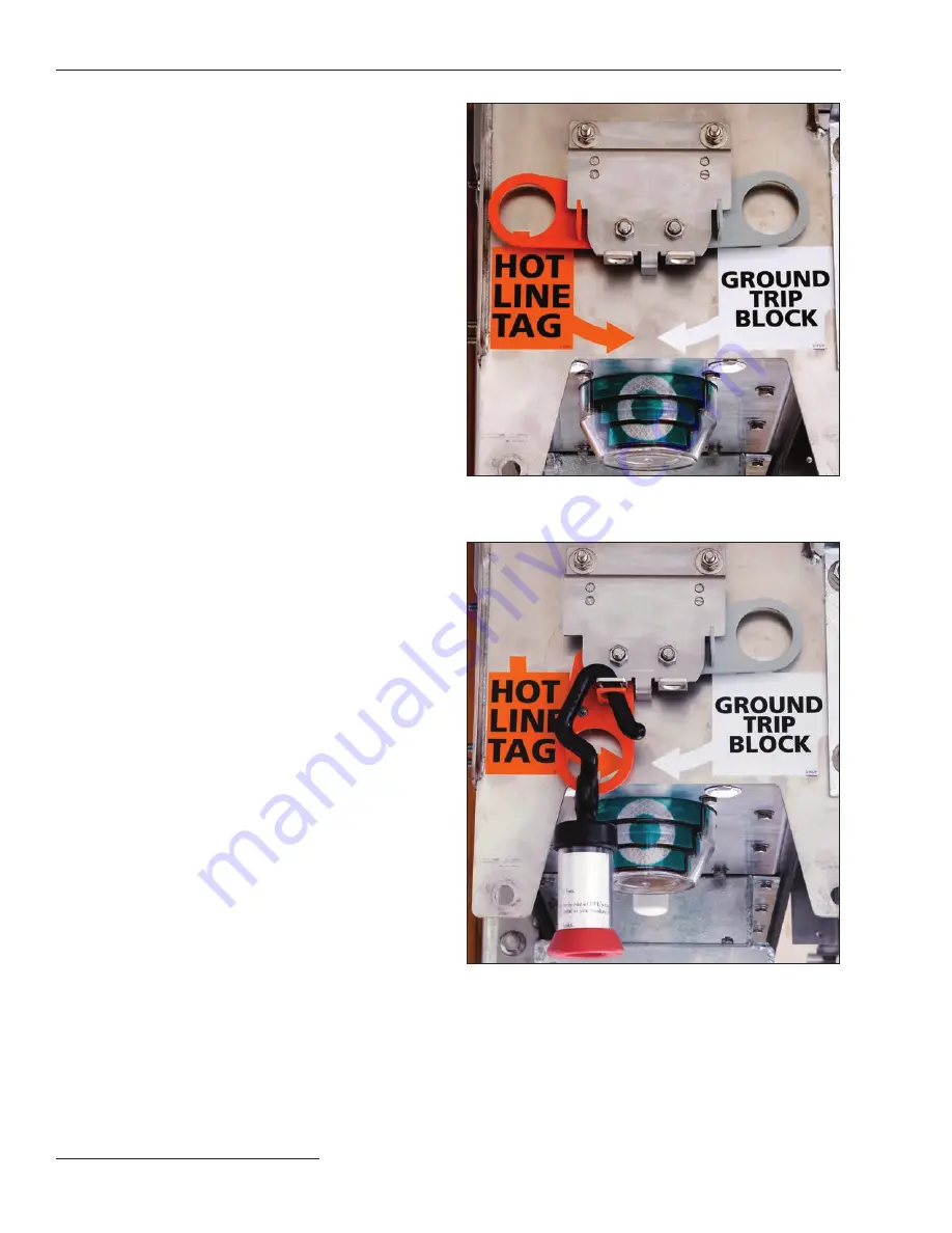
To apply a local hot line tag, pull down on the HOT
LINE TAG lever. It can be “tagged “ in this position using
conventional procedures. See Figures 28 and 29. To remove
the local hot line tag, push up on the HOT LINE TAG lever.
To remove a SCADA or IntelliLink-applied tag when a
local hot line tag has also been applied, push up on the HOT
LINE TAG lever. Then, pull down and push up on the HOT
LINE TAG lever
once, without delay
. To remove a SCADA
or IntelliLink system-applied tag when a local hot line tag
has
not
been applied, pull down and push up on the HOT
LINE TAG lever
twice, without delay
.
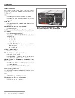
The HOT LINE TAG indicator is located on the protec-
tion and control module. See Figure 33 on page 22. When
a hot line tag is set, the HOT LINE TAG indicator flashes
for ½-second every 2 seconds. Any trip in the Hot Line Tag
profile will be performed as a three phase-trip. When the
hot line tag is removed, the indicator is
OFF
.
Manual Ground Trip Block (if furnished)
The ground trip block can be set locally with the hookstick
lever or remotely using SCADA or IntelliLink software.
A ground trip block can only be removed by the method
used to set it, and (unlike the hot line tag) the manual
lever cannot remove a ground trip block set by SCADA or
IntelliLink software.
To apply a local ground trip block, pull down on the
GROUND TRIP BLOCK lever. It can be tagged using con-
ventional procedures. See Figures 28 and 29. To remove
a local ground trip block, push up on the GROUND TRIP
BLOCK lever. The status indicator (white LED) is located
on the control module. See Figure 33 on page 22. When
a ground trip block is either set or removed, the status
indicator will light at 100% brightness for 10 seconds to
indicate that the GROUND TRIP BLOCK lever command
has been received.
With ground trip block removed overcurrent protection
will operate normally. If a ground overcurrent protection
element is configured for the active profile, it will respond
to a fault event. If a ground overcurrent element is not
configured in the active profile, removing the ground trip
block does not create a ground time-current characteristic
curve, nor does it enable the element.
Figure 28. Hot Line Tag switch and Ground Trip Block switch.
Figure 29. Hot line tag manually applied and “tagged.”

