Alignment and Adjustments
3-11
Samsung Electronics
3-4 Deck Adjustment
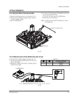
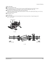
3-4-1 Operation Without Housing Assembly
1) Remove the Housing Ass’y from the Deck Ass’y.
2) Connect the Mechanical Chassis to the recorder
circuit to supply voltage.
3) Set to Unload mode.
4) Press the S/W Push (Keep ON status)to start load-
ing, and push the PLAY Key.
(Cover the Top/End sensor with black tape,
because they do not operate.)
Note
: For the removal of the Housing Ass’y refer to
4-2-2 (page 4-6).
Connceted the Recorder Circuit
SWITCH C-IN
Fig. 3-13
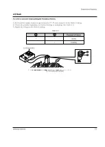
3-4-2 Setting Mechanical Mode (Without Recorder Circuit)
1) Set the power-supply output to approx. 3V~5V.
2) Choose the polarity (depending on whether load-
ing or unloading).
3) Supply the voltage to the Motor Loading, and set
to the desired mode.
Fig. 3-14
A
B
DC POWER SUPPLY
<Table 3-6>
A
B
Movement of Chassis
+
-
Unloading
-
+
Loading
Summary of Contents for VP-D455
Page 10: ...Product Specification 2 4 Samsung Electronics MEMO...
Page 30: ...3 20 Alignment and Adjustments Samsung Electronics MEMO...
Page 46: ...4 16 Disassembly and Reassembly Samsung Electronics MEMO...
Page 66: ...Exploded View and Parts List 5 20 Samsung Electronics MEMO...
Page 83: ...Samsung Electronics 8 1 8 Wiring Diagram MEMORY STICK VP D453 I D6620I VP D454 I D455 I D6650I...
Page 84: ...Wiring Diagram 8 2 Samsung Electronics MEMO...
Page 86: ...PCB Diagrams 9 2 Samsung Electronics 9 1 Main PCB COMPONENT SIDE...
Page 87: ...PCB Diagrams Samsung Electronics 9 3 L708 L704 L706 L717 L719...
Page 88: ...PCB Diagrams 9 4 Samsung Electronics CONDUCTOR SIDE Fuse 1 25A 32V...
Page 94: ...PCB Diagrams 9 10 Samsung Electronics MEMO...
Page 128: ...Troubleshooting 12 8 Samsung Electronics MEMO...
Page 140: ...Circuit Operating Description 13 12 Samsung Electronics MEMO...
Page 184: ...Reference Information 14 44 Samsung Electronics MEMO...

