Disassembly and Reassembly
4-9
Samsung Electronics
4-2-5 Sub Chassis
Note 1 : When disassembling, take care not to damage
any part. Do not stain the Rollers and Poles with oil or
grease.
Note 2 : Always remove the Sub Chassis Ass’y when
the Deck Ass’y is in unload mode.
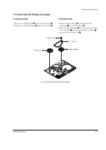
4-2-5(a) Disassembly
1) Release Sub FPC.
2) Remove 2 Screws
Œ
.
3) Lift up Sub Chassis Ass’y
´
from Main Chassis
ˇ
.
Fig. 4-13 Sub Chassis
4-2-5(b) Reassembly
1) Insert PinPart
¨
of Sub Chassis Ass’y
´
to Main
Chassis Rail
ˆ
, and then fit the reassembly part of
two place to Secure Hole
Ø
of Main Chassis Ass’y
ˇ
.
2) Secure 2 Screws
Œ
.
Note 1 : After assembling
´
with
ˇ
make sure that
Sub Chassis Ass’y
´
loads and unloads correctly by
applying 3V~5V to the Motor Loading.
Note 2 : When reassembling, confirm that pin of Arm
Review insert into the Guide Cam.
2 SCREWS
Œ
SUB CHASSIS ASS'Y
´
MAIN CHASSIS ASS'Y
ˇ
Ø
SECURE HOLE
¨
PIN
ˆ
MAIN CHASSIS RAIL
Summary of Contents for VP-D455
Page 10: ...Product Specification 2 4 Samsung Electronics MEMO...
Page 30: ...3 20 Alignment and Adjustments Samsung Electronics MEMO...
Page 46: ...4 16 Disassembly and Reassembly Samsung Electronics MEMO...
Page 66: ...Exploded View and Parts List 5 20 Samsung Electronics MEMO...
Page 83: ...Samsung Electronics 8 1 8 Wiring Diagram MEMORY STICK VP D453 I D6620I VP D454 I D455 I D6650I...
Page 84: ...Wiring Diagram 8 2 Samsung Electronics MEMO...
Page 86: ...PCB Diagrams 9 2 Samsung Electronics 9 1 Main PCB COMPONENT SIDE...
Page 87: ...PCB Diagrams Samsung Electronics 9 3 L708 L704 L706 L717 L719...
Page 88: ...PCB Diagrams 9 4 Samsung Electronics CONDUCTOR SIDE Fuse 1 25A 32V...
Page 94: ...PCB Diagrams 9 10 Samsung Electronics MEMO...
Page 128: ...Troubleshooting 12 8 Samsung Electronics MEMO...
Page 140: ...Circuit Operating Description 13 12 Samsung Electronics MEMO...
Page 184: ...Reference Information 14 44 Samsung Electronics MEMO...


