


Alignment and Adjustments
3-7
Samsung Electronics
3-3 LCD Adjustment
3-3-1 Adjustment Preparation
1) Before you start
Œ
Use the buttons on the CAMCORDER when adjusting LCD.
´
When changing the adjustment item, please press the “EASY-Q” and “DISPLAY” buttons on the
CAMCORDER.
ˇ
The adjustment value can be changed by moving the “MENU Selector” Left or Right.
¨
Press the “MENU Selector” to store each adjustment into EEPROM.
ˆ
The OSD shows “OK” after finishing each adjustment step.
Ø
In order to exit the adjustment mode, disconnect the power source.
2) Function of each buttons on the Set Key
Buttons
Description
MENU Selector push (Confirm)
Stores changed value in the adjustment and auto adjustment mode.
MENU Selector Right (Data Up)
Changes data in the adjustment state.
MENU Selector Left (Data Down)
EASY-Q (Mode Up)
Changes mode.
DISPLAY (Mode Down)
<Table 3-4>
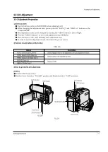
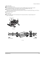
3) How to get into the LCD adjust mode
[STEP 1]
Œ
Connect the Power source.
´
Set the Power Switch to “PLAYER” position and Mode Switch to “TAPE” position.
Fig. 3-8
MENU Button
EASY Q Button
Start/Stop Button
MENU Selector
DISPLAY Button
Mode switch
PB ZOOM
Power switch
STOP Button
Summary of Contents for VP-D455
Page 10: ...Product Specification 2 4 Samsung Electronics MEMO...
Page 30: ...3 20 Alignment and Adjustments Samsung Electronics MEMO...
Page 46: ...4 16 Disassembly and Reassembly Samsung Electronics MEMO...
Page 66: ...Exploded View and Parts List 5 20 Samsung Electronics MEMO...
Page 83: ...Samsung Electronics 8 1 8 Wiring Diagram MEMORY STICK VP D453 I D6620I VP D454 I D455 I D6650I...
Page 84: ...Wiring Diagram 8 2 Samsung Electronics MEMO...
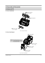
Page 86: ...PCB Diagrams 9 2 Samsung Electronics 9 1 Main PCB COMPONENT SIDE...
Page 87: ...PCB Diagrams Samsung Electronics 9 3 L708 L704 L706 L717 L719...
Page 88: ...PCB Diagrams 9 4 Samsung Electronics CONDUCTOR SIDE Fuse 1 25A 32V...
Page 94: ...PCB Diagrams 9 10 Samsung Electronics MEMO...
Page 128: ...Troubleshooting 12 8 Samsung Electronics MEMO...
Page 140: ...Circuit Operating Description 13 12 Samsung Electronics MEMO...
Page 184: ...Reference Information 14 44 Samsung Electronics MEMO...