


Circuit Operating Description
13-6
Samsung Electronics
S5C7376X (ICM01)
DSP6
DIS/JPEG/MPEG4/USB
54MHz
K4S283233F-EE75
64M DSRAM
MBM29LV160BE
(ICA03)
4M FLASH MEMORY
SMC/MS
TLV990B(ICP02)
CDS/AGC/ADC
uPD168103(ICP03)
ZOOM/FOCUS
MOTOR DRIVER
DV1 CHIP(IC201)
GLOBAL i
TMP1962(IC501)
MICOM
CCD-OUT
ZOOM MOTOR
FOCUS MOTOR
BU7806-01KV
(IC601)
AUDIO I/F
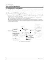
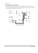
Fig. 13-4 Camera Circuit Block Diagram
13-3 H/W Function Specifications
13-3-1 Main PCB H/W Function Specifications
The main PCB records and plays back the electronically transformed video signal which comes through the
CCD of the Camera Lens Ass’y, with the audio signal in DV format on a 6.35 mm tape.
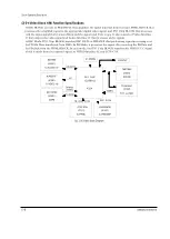
13-3-2 Camera Circuit Block H/W Function Specifications
DSP6 receives the digitized CCD signal or ITU-R656 data and outputs the video signal after going through
the color and brightness signal process. Finally, it performs encoding/decoding JPEGs at the SVGA rate and
MPEG4s at 30 FPS by using this video signal.
Using a USB 2.0 device, this compressed JPEG/MPEG data can be transferred to a PC and saved on
Flash memory cards, such as Memory Stick (Pro) and SD/MMC card.
DSP6 supplies a 54 MHz, 27MHz clock to the DV1 chip in all modes, and it processes the ITU-R656 data
as IN/OUT mode synchronized to 27MHz clock. MICOM controls the mode selection between the Memory
card mode and Camera mode.
Summary of Contents for VP-D455
Page 10: ...Product Specification 2 4 Samsung Electronics MEMO...
Page 30: ...3 20 Alignment and Adjustments Samsung Electronics MEMO...
Page 46: ...4 16 Disassembly and Reassembly Samsung Electronics MEMO...
Page 66: ...Exploded View and Parts List 5 20 Samsung Electronics MEMO...
Page 83: ...Samsung Electronics 8 1 8 Wiring Diagram MEMORY STICK VP D453 I D6620I VP D454 I D455 I D6650I...
Page 84: ...Wiring Diagram 8 2 Samsung Electronics MEMO...
Page 86: ...PCB Diagrams 9 2 Samsung Electronics 9 1 Main PCB COMPONENT SIDE...
Page 87: ...PCB Diagrams Samsung Electronics 9 3 L708 L704 L706 L717 L719...
Page 88: ...PCB Diagrams 9 4 Samsung Electronics CONDUCTOR SIDE Fuse 1 25A 32V...
Page 94: ...PCB Diagrams 9 10 Samsung Electronics MEMO...
Page 128: ...Troubleshooting 12 8 Samsung Electronics MEMO...
Page 140: ...Circuit Operating Description 13 12 Samsung Electronics MEMO...
Page 184: ...Reference Information 14 44 Samsung Electronics MEMO...