


Circuit Operating Description
Samsung Electronics
13-7
DCDC
BLOCK
PRML
BLOCK
PREAMP
BLOCK
DV1_Chip
BLOCK
AV I/F
BLOCK
CAMERA
BLOCK
TMP1962F10
(IC501)
MICOM
LB11993W
(IC401)
MOTOR
DIRVER
T/S SENSOR
REEL SENSOR
MIC SENSOR
DRUM
MOTOR
CAP.
MOTOR
LOAGDING
MOTOR
RS5C372A
(IC502)
RTC IC
RESET-IC
XC6413FY01MR
(IC503)
EEPROM
524AB0X91
(IC505)
W
U
V
FG/PG
W
U
V
FG
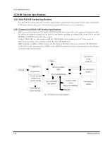
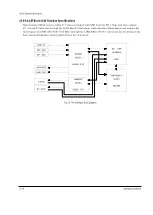
Fig. 13-5 VCR Circuit Block Diagram
13-3-3 SYSCON/SERVO Block H/W Function Specifications
MICOM IC uses 13.5 MHz for the main clock, communicates with the Camera Block and the DV1 Chip
Block, and controls each mode switching. Below are the main functions of MICOM IC:
1) Power On/Off Control
2) DV1 Chip Control/PRML Control/Audio Control
3) Input control for Function Keys and Remote Control Keys
4) IEEE 1394, LCD/CVF Control
5) Mechanism Control
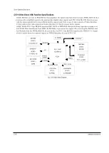
SERVO BLOCK controls the speed and phase of the DECK’s Drum Motor and Capstan Motor according to
received PWM PULSE for motor control and the On/Off control signal from MICOM. It also receives various
sensor signals (TOP/END, T/S REEL, REC PROOF, etc.), amplifies them, and outputs the signals to MICOM.
In Rec mode, DRUM SERVO controls the Drum Motor's rotation so that the video head can play back the
signal, which minimizes the phase changes. CAPSTAN SERVO regulates the Capstan Motor's rotation so
that the video head reads the recorded track accurately and can obtain the playback signal at a maximum
level. It also controls the Loading Motor with the LOADING MOTOR 4.7V VS.
Summary of Contents for VP-D455
Page 10: ...Product Specification 2 4 Samsung Electronics MEMO...
Page 30: ...3 20 Alignment and Adjustments Samsung Electronics MEMO...
Page 46: ...4 16 Disassembly and Reassembly Samsung Electronics MEMO...
Page 66: ...Exploded View and Parts List 5 20 Samsung Electronics MEMO...
Page 83: ...Samsung Electronics 8 1 8 Wiring Diagram MEMORY STICK VP D453 I D6620I VP D454 I D455 I D6650I...
Page 84: ...Wiring Diagram 8 2 Samsung Electronics MEMO...
Page 86: ...PCB Diagrams 9 2 Samsung Electronics 9 1 Main PCB COMPONENT SIDE...
Page 87: ...PCB Diagrams Samsung Electronics 9 3 L708 L704 L706 L717 L719...
Page 88: ...PCB Diagrams 9 4 Samsung Electronics CONDUCTOR SIDE Fuse 1 25A 32V...
Page 94: ...PCB Diagrams 9 10 Samsung Electronics MEMO...
Page 128: ...Troubleshooting 12 8 Samsung Electronics MEMO...
Page 140: ...Circuit Operating Description 13 12 Samsung Electronics MEMO...
Page 184: ...Reference Information 14 44 Samsung Electronics MEMO...