3-29
Samsung Electronics
CIRCUIT DESCRIPTION
Repair Manual
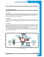
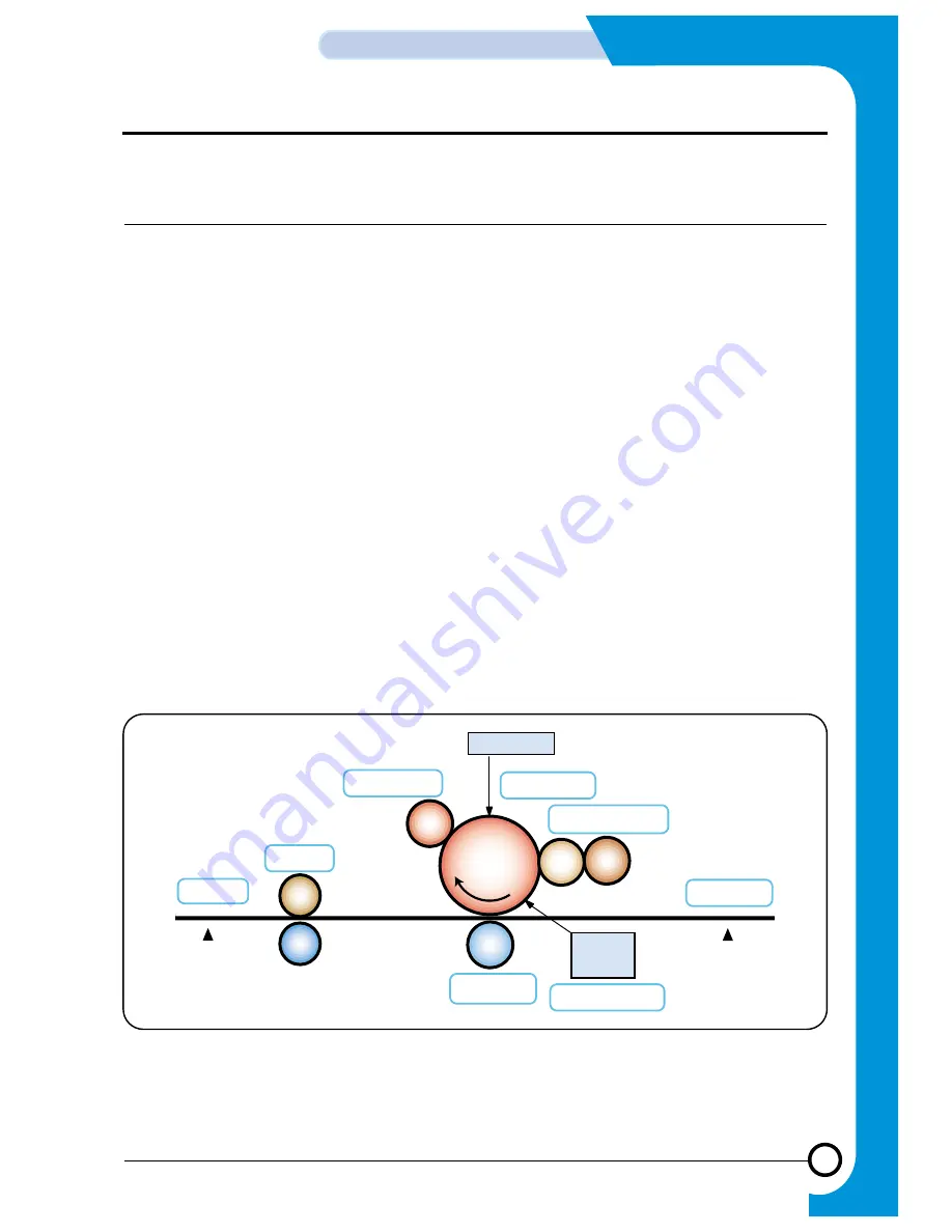
3-4-2. Developing Process
3-4-2-1 Feeder
Engine operates this unit. Solenoid rotates the feed roller and feeds one paper. Then the paper is fed into the set and hits
the actuator of the feed sensor. At this point, the engine detects the signal and prepares to spray according to the image
data. If any problem happens to this feed sensor operation, the system displays “paper jam error” on the OP panel.
Also, feed sensor unit is closely related to the paper margin.
3-4-2-2. Electrifier
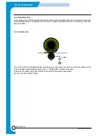
This unit electrifies consistent negative voltage to OPC. When the high negative voltage (-1550V) is allowed to charge roller,
the OPC drum surface will be consistently electrified with approxi1300V. This is the first process in generating the
digital picture.
3-4-2-3. Exposer
After receiving bitmap image data from engine board, LSU turns the laser diode either on or off depending on whether the
digital data is present or absent in order to expose the OPC drum with the switched laser beam data. The difference
between the voltages generated at this point is presented above. In other words, the part exposed to the laser will have -
50V and its relative electric potential will increase and form electrostatic latent image.
The part unexposed to the laser as it did not have the video data will consistently retain -800V. Eventually, the image will
form in the part electrified and rose to -50V(forms black dot) and the part retaining -800V will be white in order to make the
basic condition to form the video data.
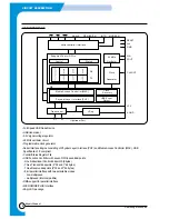
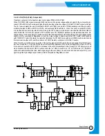
LSU
2.Charging
7.Fixing
8.Exit
EXIT
SENSOR
6.Transfer
5.Pre-Transfer
FEED
SENSOR
3.Exposure
4.Development
1.Feeding
H/R
P/R
C/R
OPC
T/R
PTL
D/R
S/R
< Engine Operating Description >
Summary of Contents for SF-530 Series
Page 87: ...Electronics ...

