3-12
CIRCUIT DESCRIPTION
Samsung Electronics
Repair Manual
Label
I/O Type
Signal Name/Description
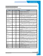
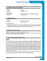
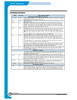
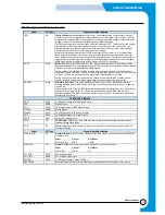
TELEPHONE LINE INTERFACE/AUXILIARY
TXA1, TXA2
O(DD)
Transmit Analog 1 and 2. The TXA1 and TXA2 outputs are differential outputs 180 degrees out of phase
with each other. Each output can drive a 300
load.
RIN
O(DA)
Receive Analog. RIN is a single-ended receive data input from the telephone line interface or an optional
external hybrid circuit.
RINGD
IA
Ring Detect. The RINGD input is monitored for pulses in the range of 15 Hz to 68 Hz. The frequency
detection range may be changed by the host in DSP RAM. The circuit driving RINGD should be a 4N35
optoisolator or equivalent. The circuit driving RINGD should not respond to momentary bursts of ringing
less than 125 ms in duration, or less than 40 VRMS (15 Hz to 68 Hz) across TIP and RING. Detected ring
signals are reflected on the /RI output signal as well as the RI bit.
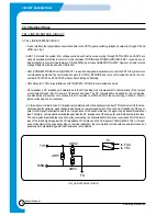
/TALK
O(DD)
Relay B Control. The /TALK open collector output can directly drive a +5V reed relay coil with a minimum
resistance of 360 ohms (13.9 mA max. @ 5.0V) and a must-operate voltage no greater than 4.0 VDC. A
clamp diode, such as a 1N4148, should be installed across the relay coil. An external transistor can be
used to drive heavier loads (electro-mechanical relays). /TALK is controlled by host setting/resetting of the
RB bit.
In a typical application, /TALK is connected to the normally closed Tal k/Data relay (/TALK). In this case,
/TALK active opens the relay to disconnect the handset from the telephone line.
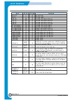
OH
O(DD)
Relay A Control. The OH open collector output can directly drive a +5V reed relay coil with a minimum
resistance of 360 ohms (13.9 mA max. @ 5.0V) and a must-operate voltage no greater than 4.0 VDC. A
clamp diode, such as a 1N4148, should be installed across the relay coil. An external transistor can be
used to drive heavier loads (electro-mechanical relays). OH is controlled by host setting/resetting of the RA
bit.
In a typical application, OH is connected to the normally open Off-Hook relay (OHRC). In this case, OH
active closes the relay to connect the modem to the telephone line.
Alternatively, in a typical application, OH is connected to the normally open Caller ID relay (CALLID). When
the modem detects a Calling Number Delivery (CND) message, the OH output is asserted to close the
CALLID relay in order to AC couple the CND information to the modem RIN input (without closing the off-
hook relay and allowing loop current flow which would indicate an off-hook condition).
/RI
OA
Ring Indicator. /RI output follows the ringing signal present on the line with a low level (0 V) during the ON
time, and a high level (+3.3 V) during the OFF time coincident with the ringing signal. The RI status bit
reflects the state of the /RI output.
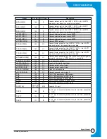
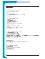
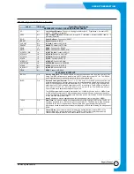
DIAGNOSTIC SIGNALS
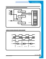
Three signals provide the timing and data necessary to create an oscilloscope quadrature eye pattern. The
eye pattern is a display of received baseband constellation. By observing this constellation, common line
disturbances can usually be identified.
EYEXY
OA
Serial Eye Pattern X/Y Output. EYEXY is a serial output containing two 11-bit diagnostic words (EYEX
and EYEY) for display on the oscilloscope X axis (EYEX) and Y axis (EYEY). EYEX is the first word clocked
out; EYEY follows. Each word has 8-bits of significance. EYEXY is clocked by the rising edge of EYECLK.
This serial digital data must be converted to parallel digital form by a serial-to-parallel converter, and then to
analog form by two digital-to-analog (D/A) converters.
EYECLK
OA
Serial Eye Pattern Clock. EYECLK is a 336 kHz output clock for use by the serial-to-parallel converters.
The low-to-high transitions of RDCLK coincide with the low-to-high transitions of EYECLK. EYECLK,
therefore, can be used as a receiver multiplexer clock.
EYESYNC
OA
Serial Eye Pattern Strobe. EYESYNC is a strobe for loading the D/A converters.
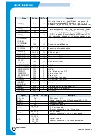
SPEAKER INTERFACE
SPKR
O(DF)
Speaker Analog Output. The SPKR output reflects the received analog input signal. The SPKR on/off and
three levels of attenuation are controlled by bits in DSP RAM. When the speaker is turned off, the SPKR
output is clamped to the voltage at the VC pin. The SPKR output can drive an impedance as low as 300
ohms. In a typical application, the SPKR output is an input to an external LM386 audio power amplifier.
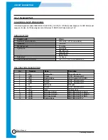
FM336 Signals Definitions
Summary of Contents for SF-530 Series
Page 87: ...Electronics ...


