3-24
CIRCUIT DESCRIPTION
Samsung Electronics
Repair Manual
3-2 OPE PBA
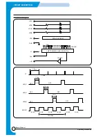
3-2-1 SUMMARY
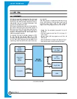
Scan
Position
Sensor
Document
Detect
Sensor
Connector
MICOM
HT48C5A
UART
Reset
11
7
X
Y
8
RESONATOR
7.37 MHz
LCD
16x 1Line
Key Matrix
LEDs
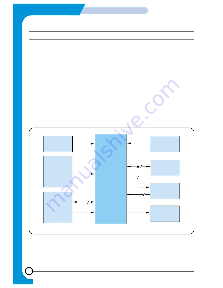
OPE Board is separated functionally from the main board
and operated by the micom(HT48C5A) in the board. OPE
and the main use UART (universal asynchronous receiv-
er/transmitter) channel to exchange information. OPE
reset can be controlled by the main.
OPE micom controls key-scanning and LCD and LED dis-
play, detects documents and senses SCAN position. If
there occurs an event in OPE (such as key touch and sen-
sor level change), it sends specific codes to the main to
respond to the situation and the main analyzes these
codes and operates the system.
For example, it the main is to display messages in OPE,
the main transmits data through UART line to OPE
according to the designated format and OPE displays this
on LCD, LED. OPE’s sensing is also transmitted to the
main through UART line and then the main drives neces-
sary operation.
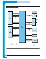
OPE PBA consists of U1(MICOM, HT48C5A),LCD, key
matrix, LED indicators, SCAN position sensor and the
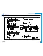
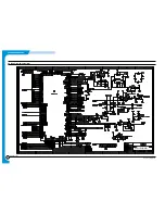
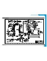
document detect sensor. Refer to OPE Schematic
Diagram and Wiring Diagram sections of this manual.
• Display from the controller is received at U2 pin 47
(RX DATA).
• LCD drive signals are sent from P1-x pin group, P1-
4~P1-14 pins.
• Machine status LED drive signals are sent from U2
LED0~LED4.
• Document detect sensor output is received at U2 pin 1.
• Scan position sensor output is received at U2 pin7
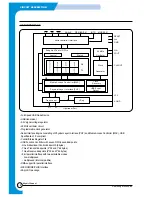
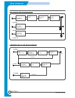
<OPE BLOCK DIAGRAM>
Summary of Contents for SF-530 Series
Page 87: ...Electronics ...

