
96
13. Safety Instructions on Service
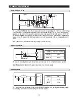
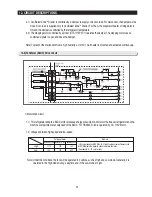
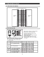
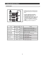
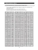
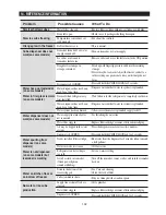
13-3) Check a load
Load
Measuremenr Termina l
Value
Contents
Ice Solenoid Valve
Auger Motor
Cube Solenoid Valve
1) Dispenser heater
2) Water tank heater
Ref. Def heater
Freezer Def heater
between CN70 13
and CN70 7
between CN70
9 and CN70 7
between CN70
11 and CN70 1
between CN71
5 and CN70 11
between CN71
3 and CN70 11
between CN71
1 and CN70 11
0
Ω
∞Ω
0
Ω
∞Ω
0
Ω
∞Ω
0
Ω
∞Ω
0
Ω
∞Ω
0
Ω
∞Ω
Temperature fuse, heater, wires short trouble
Temperature fuse, heater, wires disconnection trouble
Temperature fuse, heater, wires short trouble
Temperature fuse, heater, wires disconnection trouble
Heater, wires short trouble
Heater, wires, and connector disconnection
Coil, wires short trouble
Coil, wires disconnection trouble
Coil, wires short trouble
Coil, wires disconnection trouble
Coil, wires short trouble
Coil, wires disconnection trouble
Unplug the powercord and disconnect the
main PCB CN70 and CN71, the measure the
follows :
1. As shown in table below, measure the
resistance between terminals, check load
trouble and wire connection error.
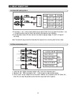
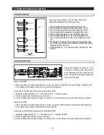
2. The diagram of circuit was drawn based on the
maximum load. When a repair is needed, see
the electric wiring diagram on the back of
refrigerator to troubleshoot the corresponding
model.
3. For safety, you must turn the power off.
Summary of Contents for RS265BBWP
Page 18: ...18 Refrigerator 2 PRODUCT SPECIFICATIONS 2 9 Cooling Air Circulation Freezer...
Page 68: ...7 EXPLODED VIEW PARTS LIST 7 3 Cabinet 7 1 69...
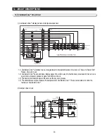
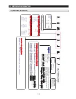
Page 78: ...79 8 BLOCK DIAGRAM...
Page 79: ...80 9 WIRING DIAGRAM 9 1 RS265BB RS267BB RS267LB RS269LB...
Page 80: ...81 9 WIRING DIAGRAM 9 2 RS263BB RS265LB...
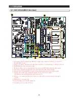
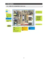
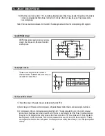
Page 82: ...83 10 PCB DIAGRAM 10 2 CONNECTOR ARRANGEMENT Main Board...
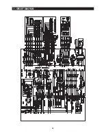
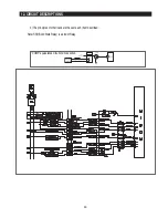
Page 83: ...84 11 CIRCUIT DIAGRAM...


