


88
11. CIRCUIT DESCRIPTIONS
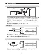
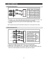
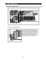
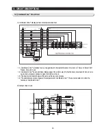
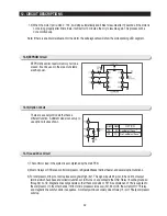
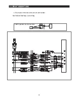
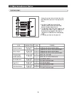
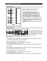
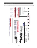
12-6) Key Scan and Display Circuit
1) Key Scan and display operation.
The model uses a decorder IC which 4 inputs and 9 outputs.
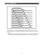
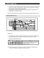
If the IC 9 decorder (TC4028BP) received signals from
MICOM pins (3
∼
6), an output signal per 2 miliseconds
comes out from Q3, Q41, Q8, Q6, Q9, Q7, Q0, Q2, and Q4
pin in sequence. This signal enters to a driver IC input
terminal of the CoolSelect Zone
TM
PCB and IC5 (TD
62783AP), then approximate 11V peaks will generate from
an output terminal as shown on the next page.
Summary of Contents for RS265BBWP
Page 18: ...18 Refrigerator 2 PRODUCT SPECIFICATIONS 2 9 Cooling Air Circulation Freezer...
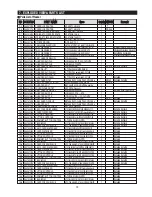
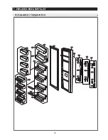
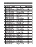
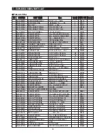
Page 68: ...7 EXPLODED VIEW PARTS LIST 7 3 Cabinet 7 1 69...
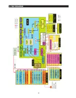
Page 78: ...79 8 BLOCK DIAGRAM...
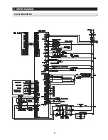
Page 79: ...80 9 WIRING DIAGRAM 9 1 RS265BB RS267BB RS267LB RS269LB...
Page 80: ...81 9 WIRING DIAGRAM 9 2 RS263BB RS265LB...
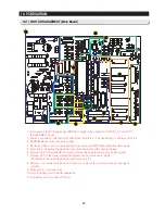
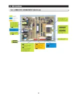
Page 82: ...83 10 PCB DIAGRAM 10 2 CONNECTOR ARRANGEMENT Main Board...
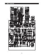
Page 83: ...84 11 CIRCUIT DIAGRAM...


