
95
13. Safety Instructions on Service
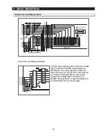
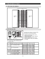
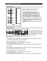
13-1) Wire connector on the cabinet door.
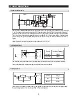
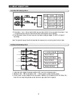
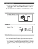
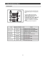
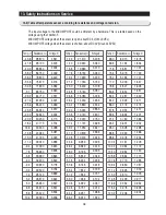
13-2) How to check relay failure
Div. of contact Voltage at both terminal of coil and trigger Both terminals of contact
Resistance value
3-contact
terminal
Relay
0
Ω
(Short) -> Normal
∞
Ω
(Open) -> Normal
∞
Ω
(Open) -> Normal
0
Ω
(Short) -> Normal
0
Ω
(Short) -> Normal
∞
Ω
(Open) -> Normal
About 4-5
㏀
(Short) -> Normal
∞
Ω
(Open) -> Normal
Between C and NO
Between C and NC
Between C and NO
Between C and NC
Between both terminals of contact
Between both terminals of contact
Between both terminals of contact
Between both terminals of contact
DC 12V (Working Condition)
DC 0V (Stop Condition)
∼
DC 12V (load working condition)
∼
DC 0V (load stop condition)
∼
DC 12V (load working condition)
∼
DC 0V (load stop condition)
2-contact
terminal
Relay
SSR
Disconnect the connector of the main PCB
CN70 and CN71, then check the follows :
1. Measure the voltage at both terminals of a coil and
determine if the relay is working.
2. Measure the voltage at both terminals of a trigger and
determine if SSR is working.
3. Measure the resistance at both terminals of a load
contact, and determine if there is an error in voltages of
coil and trigger.
Note) NC -> Normally Close (C terminal and ON terminal)
NO -> Normally Open (C terminal and Open terminal)
C -> Common Terminal
Summary of Contents for RS265BBWP
Page 18: ...18 Refrigerator 2 PRODUCT SPECIFICATIONS 2 9 Cooling Air Circulation Freezer...
Page 68: ...7 EXPLODED VIEW PARTS LIST 7 3 Cabinet 7 1 69...
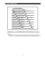
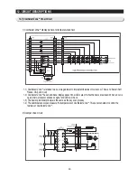
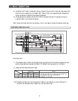
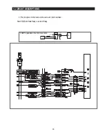
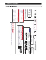
Page 78: ...79 8 BLOCK DIAGRAM...
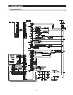
Page 79: ...80 9 WIRING DIAGRAM 9 1 RS265BB RS267BB RS267LB RS269LB...
Page 80: ...81 9 WIRING DIAGRAM 9 2 RS263BB RS265LB...
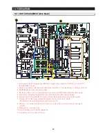
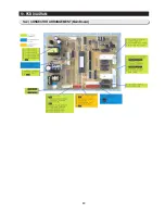
Page 82: ...83 10 PCB DIAGRAM 10 2 CONNECTOR ARRANGEMENT Main Board...
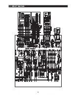
Page 83: ...84 11 CIRCUIT DIAGRAM...


