


20
3. OPERATING INSTRUCTIONS & INSTALLATION
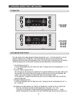
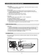
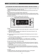
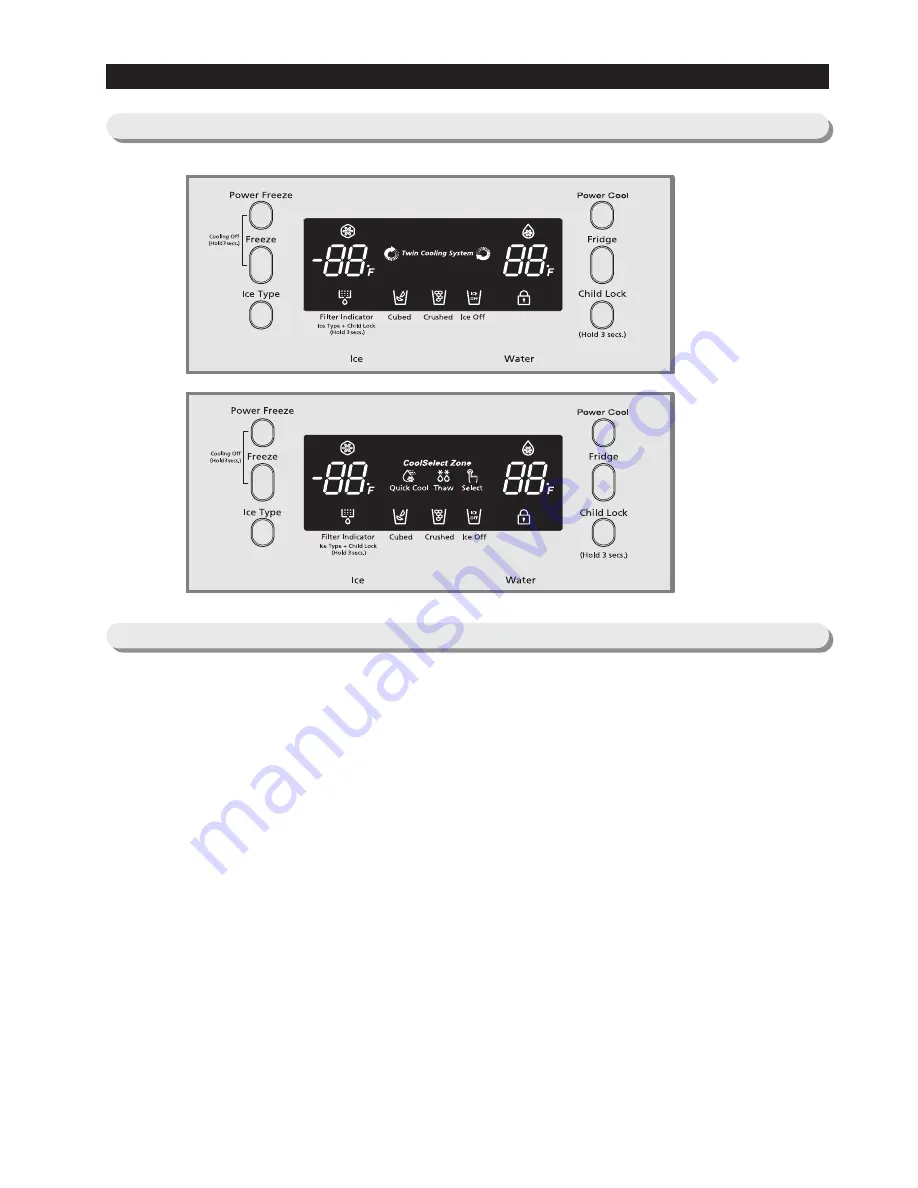
3-1) Digital Panel
When the system power is initally engaged, the default set temperature are -4
℉
for the freezer and 38
℉
for the set
refrigerator, respectively. The numbers shown on the digital display panel stand for the actual compartments
temperatures. When the compartment temperatures go down, so do the numbers on the display panel, and finally they
reach the set temperatures. Once the system is stabilized, the display temperatures are the set temperature.
1) Freezer Temperature Control.
To select a set temperature, press the Freezer Temp. button. The display shows the set temperature from -14
℉
to
8
℉
in sequence.
2) Quick Ice Freezer Temperature Control
Interior Temperature of the freezer will be controlled with -14 degrees Fahrenheit until the ice bucket is filled up with
ice cubes. When the ice bucket is filled up with ice cubes, the freezer will run with original set temperature. Also,
whenever the ice bucket is released from being filled with ice cube, the freezer will repeat
to be controlled with -14 degrees Fahrenheit. But if you select "Ice Off, the freezer always will be controlled with
original set temperature.
3) Refrigerator Temperature Control.
To select a set temperature, press the Fridge Temp. button. The display shown the set temperature from 34
℉
to
46
℉
in sequence.
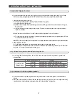
note) Because of the temperature sensor sensivity, the refrigerator can be under and/or over cooled when
the air flow is blocked by stored foods. (Temperature range of the sensor : 15
℉∼
80
℉
)
In the event of a power failure, if the freezer temperature is maintained lower than 41
℉,
the last
selected set temperature and functions memorized in EEPROM will be restored when the power is on.
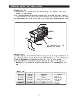
for
RS263BB
RS265LB
for
RS265BB
RS267BB
RS267LB
RS269LB
3-2) Temperature Control Function
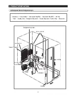
Summary of Contents for RS265BBWP
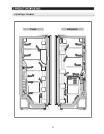
Page 18: ...18 Refrigerator 2 PRODUCT SPECIFICATIONS 2 9 Cooling Air Circulation Freezer...
Page 68: ...7 EXPLODED VIEW PARTS LIST 7 3 Cabinet 7 1 69...
Page 78: ...79 8 BLOCK DIAGRAM...
Page 79: ...80 9 WIRING DIAGRAM 9 1 RS265BB RS267BB RS267LB RS269LB...
Page 80: ...81 9 WIRING DIAGRAM 9 2 RS263BB RS265LB...
Page 82: ...83 10 PCB DIAGRAM 10 2 CONNECTOR ARRANGEMENT Main Board...
Page 83: ...84 11 CIRCUIT DIAGRAM...


