


87
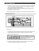
12. CIRCUIT DESCRIPTIONS
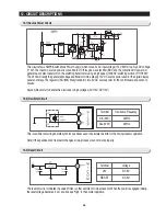
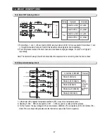
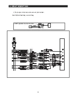
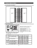
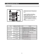
12-4) Door S/W Sensing Circuit
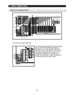
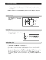
12-5) Temperature Sensing Circuit
1) The terminals,
②
and
⑥
of the connector (CN30) are grounded, and DC5V (Vcc) is supplied to the terminals,
⑤
and
⑥
through the resistors, R404 and R403 for the freezer and the refrigerator door, respectively.
2) The micro-processor senses the door’s open and close based on engaged voltages, “Low(0V)” and “High(5V),”
respectively.
Note) The door switch always should be checked when the evaporator fan is not running while the door is closed.
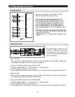
Terminal
Operation
Volt(state)
Freezer
DOOR CLOSE
DOOR OPEN
0V (LOW)
5V (HIGH)
Ref.
DOOR CLOSE
DOOR OPEN
0V (LOW)
5V (HIGH)
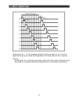
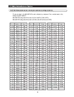
# of terminal in MICOM
Remark
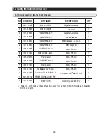
PIN #49 (F-SENSOR)
PIN #50 (F-DEF-SENSOR)
PIN #52 (R-SENSOR)
PIN #53 (R-DEF-SENSOR)
PIN #56 (EXT-SENSOR)
Micom
terminal
voltage may
change
according to
temp.
1) A thermistor with a negative temperature coefficient (NTC) is used for a temperature sensor.
2) Resistors, R 306
∼
R310 and capacitors, C 301
∼
C 305 are used for a noise protection purpose.
3) For the F-sensor, the input voltage into the micro processor (MICOM), VF is calculated by (Rth x Vcc)/(R303+ Rth),
where Rth is a corresponding resistance to the thermistor’s output (See Ref. 6 in Appendix).
Summary of Contents for RS265BBWP
Page 18: ...18 Refrigerator 2 PRODUCT SPECIFICATIONS 2 9 Cooling Air Circulation Freezer...
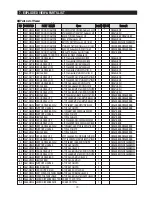
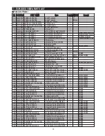
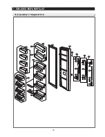
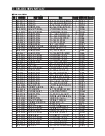
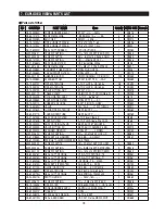
Page 68: ...7 EXPLODED VIEW PARTS LIST 7 3 Cabinet 7 1 69...
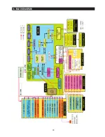
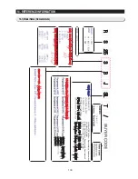
Page 78: ...79 8 BLOCK DIAGRAM...
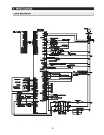
Page 79: ...80 9 WIRING DIAGRAM 9 1 RS265BB RS267BB RS267LB RS269LB...
Page 80: ...81 9 WIRING DIAGRAM 9 2 RS263BB RS265LB...
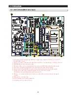
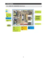
Page 82: ...83 10 PCB DIAGRAM 10 2 CONNECTOR ARRANGEMENT Main Board...
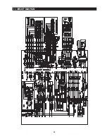
Page 83: ...84 11 CIRCUIT DIAGRAM...


