

92
12. CIRCUIT DESCRIPTIONS
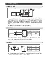
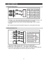
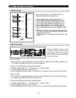
12-10) Option Circuit
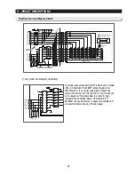
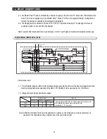
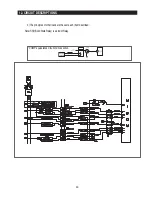
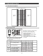
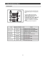
12-11) Load Drive Circuit
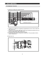
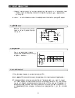
12-9) EEPROM Circuit
EEPROM is semiconductor memory not to be
erased. It can be used in the area of unstable
electric power.
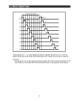
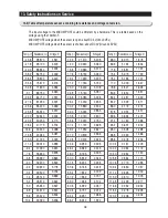
1-3) When the motor rpm is in 600
∼
700, it will stop automatically and it tries to resume after 10 seconds. If the motor is
not working properly after 5 time trials, it will rest for 10 minutes, then try to resume again. This process will be
done continuously.
Note) If there is an abnormal situation for the motor, the self-diagnostics will show the corresponding LED segment.
1) The control of load in the system is accomplished by the main PCB.
2) Most of relays or SSRs can control compressor, refrigerator/freezer defrost heater, and several option functions.
3) For compressor, #18 pin of micro processor signals High (5V). This signal inputs #5 pin of IC3 and #14 of output
terminal which have base and collector functions of IC3 turns on and connects the GND. Relay 73 will be grounded
through #14 of IC. Magnetic lines will generate so that the second side of RY73 is activated and 115V is supplied to
the compressor. On the other hands, if #18 of micro processor turns Low(0V), #5 of IC3, the current of RY 73 relay,
and magnetic line will shut down in sequence. A contact point in secondary side of Relay 73 is off. Finally compressor
will stop.
There are a variety of models that have a
different function. A different model can set up to
use option circuit as shown.
X
X
X
O
D601 D602
OPTION
CoolSelect Zone
TM
No CoolSelect Zone
TM
Summary of Contents for RS265BBWP
Page 18: ...18 Refrigerator 2 PRODUCT SPECIFICATIONS 2 9 Cooling Air Circulation Freezer...
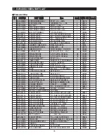
Page 68: ...7 EXPLODED VIEW PARTS LIST 7 3 Cabinet 7 1 69...
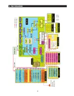
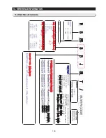
Page 78: ...79 8 BLOCK DIAGRAM...
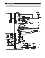
Page 79: ...80 9 WIRING DIAGRAM 9 1 RS265BB RS267BB RS267LB RS269LB...
Page 80: ...81 9 WIRING DIAGRAM 9 2 RS263BB RS265LB...
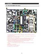
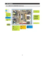
Page 82: ...83 10 PCB DIAGRAM 10 2 CONNECTOR ARRANGEMENT Main Board...
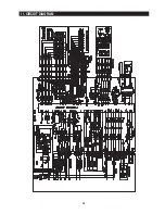
Page 83: ...84 11 CIRCUIT DIAGRAM...


