


89
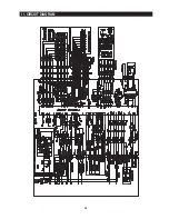
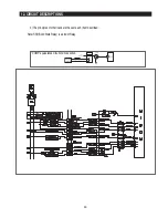
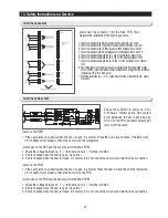
12. CIRCUIT DESCRIPTIONS
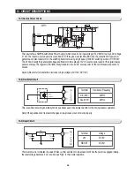
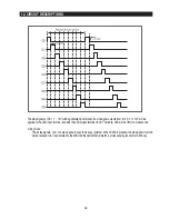
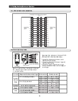
The step signals of DC 11
∼
12V will be generated periodically. If a sink signal outputs from IC4, DC 11-12V will be
applied to the LED input terminal and sink the LED output terminal to 0V. Therefore, LED will be ON for 2 miliseconds.
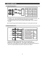
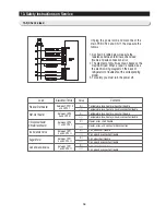
2) Key Scan
The 6 step signals, Q6
∼
Q4 are applied to scan the 6 keys (buttons). When SW6 is pressed, the step signal from Q6
will be reduced to 5V and entered to the MICOM, then MICOM will match a corresponding function for SW6 key.
Summary of Contents for RS265BBWP
Page 18: ...18 Refrigerator 2 PRODUCT SPECIFICATIONS 2 9 Cooling Air Circulation Freezer...
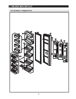
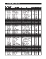
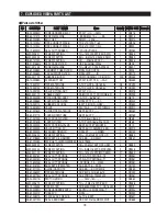
Page 68: ...7 EXPLODED VIEW PARTS LIST 7 3 Cabinet 7 1 69...
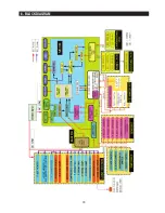
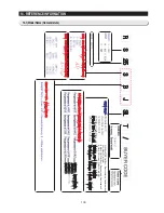
Page 78: ...79 8 BLOCK DIAGRAM...
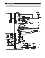
Page 79: ...80 9 WIRING DIAGRAM 9 1 RS265BB RS267BB RS267LB RS269LB...
Page 80: ...81 9 WIRING DIAGRAM 9 2 RS263BB RS265LB...
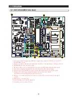
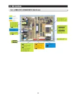
Page 82: ...83 10 PCB DIAGRAM 10 2 CONNECTOR ARRANGEMENT Main Board...
Page 83: ...84 11 CIRCUIT DIAGRAM...


