Saluki SE2031 User Manual Download Page 88

Tel: 886. 909 602 109 Email: [email protected]

www.salukitec.com

88

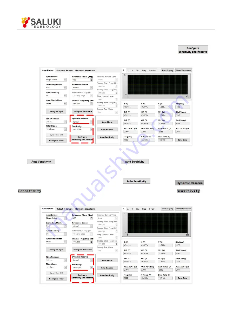
4. Choose these two options in

Reserve & Sensitivity Configuration

, including

Dynamic Reserve

and

Sensitivity

with other options in default, as is shown in Fig.74. At last, click the button

to

finish the configurations.

Fig.74 Reserve & Sensitivity Configuration

Use “

” to set sensitivity. Click the button

in Auto Sensitivity option. Then this

button displays

Processing

…”

This means the SE2031 is executing auto sensitivity function. And after finishing

this function, this button will reset to the original status

. Now the

and

options will update to the values returned by SE2031. At this time, the

option

change to a suitable one contrasting with Fig.74, as is shown in Fig.75.

Fig.75 Auto Sensitivity Configuration

Summary of Contents for SE2031

Page 1: ...SE2031 Digital Lock in Amplifier User Manual Saluki Technology Inc...

Page 2: ...salukitec com 2 The document applies to following models SE2031 DSP Lock in Amplifier 1 mHz to 3 MHz Standard Pack 1 Main Machine 1 Power Cord 1 USB Cable 2 BNC Connection Cable 1 Spare Fuse 2A 250VA...

Page 3: ...itted for the purpose of making profit without its prior permission otherwise Saluki will reserve the right to investigate and affix legal liability of infringement Product Quality Assurance The warra...

Page 4: ...ntrinsic Noise Sources 17 1 11 External Noise Sources 19 1 12 Aux In Out 21 1 13 Sweep Frequency and Amplitude of Signal Generator 21 1 14 Harmonic Wave Measurement 22 2 Interfaces 23 2 1 Front Panel...

Page 5: ...93 6 4 Amplitude Accuracy and Flatness 94 6 5 Amplitude Linearity 95 6 6 Frequency Accuracy 96 6 7 Sine Output Amplitude Accuracy and Flatness 96 6 8 DC Outputs and Inputs 97 6 9 Input Noise 99 6 10...

Page 6: ...ifiers will amplify both the noise signals and the required signals If there is no band limiting or filtering amplification will decrease the signal to noise ratio SNR Therefore filtering is needed to...

Page 7: ...s part is zero In the frequency region we can redraw these three parts The first part is at 0Hz which is known as the DC component of one signal The second part is at 2fref Hz The third part is a rand...

Page 8: ...de control signal which is associated with the detected signal The SE2031 reference input can trigger on an analog signal such as a sine wave or a TTL logic signal The input is AC coupled and the inpu...

Page 9: ...The PSD in the SE2031 acts as a digital multiplier as is shown in Fig 5 The input signal amplified and filtered is converted to digital signal by a 24 bits A D converter and then goes into the PSD The...

Page 10: ...requency Only the signal whose frequency is exactly equal to the reference frequency will result in a DC output The low pass filter LPF at the PSD output removes all the AC signals that unwanted inclu...

Page 11: ...ause the capacitors required for the RC filters are prohibitively large in value and size Why would you use such a long time constant Sometimes you have no choice If the reference is below 1 Hz with a...

Page 12: ...nal and the setting scale Otherwise the SE2031 shows the values of CH1 and CH2 on the front panel including the value of X Y R of the test signal The display interface of SE2031 is shown in Fig 6 SE20...

Page 13: ...ale When the sensitivity is changed the percentage does not change The X Y and R outputs can be expanded It s realized by multiplying the output with an expansion factor Thus a signal which is only 10...

Page 14: ...ecomes part of the DC signal after the PSD This enlarges the output error of the lock in amplifier The dynamic reserve is related to noise frequency The dynamic reserve is 0dB at reference frequency a...

Page 15: ...er sees Hz Vrm 10 of input noise and has an ENBW of 1 4 100ms or 2 5 Hz The voltage noise at the filter output will be Hz Hz Vrm 5 2 3 or 4 7 Vrms For Gaussian noise the peak peak noise is about 5 tim...

Page 16: ...the highest signal frequency is 100 kHz then the sampling frequency is 312 5 kHz However signals above 156 kHz cannot reach the A D converter These signals would violate the Nyquist criterion and be u...

Page 17: ...his mode take care that the two cables travel the same path between the experiment and the lock in There should not be a large loop area enclosed by the two cables Otherwise measurement is susceptible...

Page 18: ...57 nA which is about 0 000006 of Idc At a smaller current the fluctuation is larger For example if Idc is 1 A and B is still 10 kHz then I is about 0 006 or 85 dB If Idc is 1 pA then I is about 5 6 or...

Page 19: ...lated to the reference If they are picked up in the signal noise will add or subtract from the actual signal and cause errors in the measurement Fortunately external noise sources can be reduced throu...

Page 20: ...ound voltage can cause the ground current flow in the ground loop Since the ground is with low impedance noise current is always very high Cures for ground loop problems include 1 Connect all grounds...

Page 21: ...internal differential signal The input impendence is 1 M At the same time they can pick up signals to measure slow analog signal or DC signals the signals come from temperature sensor and pressure se...

Page 22: ...be described as the linear combination of one constant and many sine or cosine functions with the base frequency and the multiple frequencies The constant is the DC component The base frequency compon...

Page 23: ...ose different setting options and another is to highlight some parameters and then use the knob or keyboard to input For all functions soft key only work with parameters that are adjacent to it Spin K...

Page 24: ...This power connector with a build in fuse receives 220 V 50 Hz AC power And it can filter high frequency noise USB The SE2031 lock in amplifier communicates with the PC through a USB interface so that...

Page 25: ...esults of measurement If Display is lighted see the Status 1 If another menu bar is lighted see the Status 2 Sens The value of sensitivity Filter The value of the filter roll off Notch The status of n...

Page 26: ...o optional such as number chart bar chart XY coordinate graph and pole coordinate graph More details about setting is in DISPLAY submenu 3 Monitoring Bar The monitoring bar is at the bottom of the scr...

Page 27: ...nt over voltage damage to the instrument Freq Display the frequency of input signal Ref Source The mode of the reference signal Internal or External PLL The status of PLL If the internal reference is...

Page 28: ...ukitec com www salukitec com 28 As is shown in Fig 15 users can choose different functions in the function bar It s operated by 5 soft keys which are make different sense in different submenu This is...

Page 29: ...fferential voltage input mode I Current input mode Note that when choose mode A and mode A B the amplitude of the input signal must be less than 1Vrms 3 1 2 Current Gain Setting the Current Gain 1M Th...

Page 30: ...ed DC DC coupling input mode In this mode the AC component of the input signal will be eliminated If the signal frequency is less than 200 Hz DC should be chosen 3 1 5 Line Notches Setting the Status...

Page 31: ...he phase range is from 180 to 180 After the accuracy PLL lock the phase of the reference signal REF IN the signal will be the phase standard and that is default in this system Other phase values are r...

Page 32: ...us it is beneficial to choose Sine to trigger Moreover choose TTL signal if the signal frequency is very low 1Hz If the input reference signal is sine wave choose SINE to trigger In this mode the inst...

Page 33: ...Hz Sweep Set Setting frequency sweep parameters Start the start frequency of sweep Stop the cutoff frequency of sweep Step in the Linear mode the Step is the step frequency in the Log mode the Step i...

Page 34: ...imitation of the harmonic setting is Harmonic Freq 3MHz where Freq means the reference frequency Once beyond the limit system will reduce the order of harmonic automatically to meet the conditions At...

Page 35: ...eference signal is generated by the oscillator in SE2031 The TTL OUT BNC connector on rear panel will output TTL signal which is synchronous with the Sine Output Fig 22 Sine Output Secondary Submenu F...

Page 36: ...ep Frequency and time The range of amplitude is from 0 001 Vpp to 5 Vpp Start amplitude is 1 0 Vpp in default and Stop amplitude is 5 000 Vpp in default The minimum resolution of the amplitude is 0 00...

Page 37: ...V nA 1 V A The change of Sensitivity will change the dynamic range of the system Besides it will impact the output of CH1 CH2 If the measure signal is current the full scale acts as the corresponding...

Page 38: ...0 46 125 25 1 25 2 mV 14 28 54 125 25 1 25 1 mV 10 34 60 500 25 1 25 500 V 16 40 66 1250 25 1 25 200 V 24 48 74 1250 25 1 25 100 V 14 54 80 2500 25 1 25 50 V 20 60 86 2500 25 1 25 20 V 28 68 94 2500 2...

Page 39: ...is same the greater the roll of slope of filter is the smaller the time constant is And this will cause faster response 3 3 5 Synchronous Setting the Status of the Synchronous Filter OFF Close the syn...

Page 40: ...tus will be shown in the status bar at the top left of the screen such as Sensitivity Filter and so on Output The real time values of R X Y and will be shown at the top left status bar Input There are...

Page 41: ...ng to the actual R value and draw as is shown in Fig 26 its angle according to the value 2 Chart XY coordinates chart It displays the curve of the measurement results Users can watch the value of samp...

Page 42: ...n Type including Bar and Chart If Type chooses Bar Trace provides options including fundamental wave harmonic and Equation If Type chooses Chart Trace provides options Buffer1 Buffer2 Buffer3 and Buff...

Page 43: ...l harmonic of the input signal Xh2 The X value of 2th channel harmonic of the input signal Yh2 The Y value of 2th channel harmonic of the input signal Rh2 The R value of 2th channel harmonic of the in...

Page 44: ...A Equation When the Trace options in DISPLY submenu switch to E1 the display result is the calculate result of the Equation 1 In Bar display mode the display range is from 0 000001 to 9999999 without...

Page 45: ...he value of Range Set Range 1 00e 03 1mV then the display range is 1mV to 1mV Curve Point Setting the position of sampling curve In Curve Point mode the Cursor in Chart can rapidly locate position and...

Page 46: ...se the current parameters and status can be save in S1 Save Recall choose Recall Channel chooses S1 and Execute choose YES to recall the archive In this case the data in S1 can be recalled 3 6 CHANNEL...

Page 47: ...10V 5 corresponds to 5V c frequency Every stage of the frequency is from 5V to 10V For example 1000Hz 5 V 1200Hz 6 V 1600Hz 8 V 1800Hz 9 V 1990Hz 9 95 V 2000Hz 5 V next stage The frequency is divided...

Page 48: ...ut h2 the corresponding analog level of the channel output E1 the corresponding analog level of the channel output E2 the corresponding analog level of the channel output E3 the corresponding analog l...

Page 49: ...AMPLE menu should cooperate with the keys in CONTROL area In this case SAMPLE can control the sample to start pause and reset Fig 36 SAMPLE Submenu 3 7 1 Step Time Setting the Sampling Invertal Settin...

Page 50: ...Mode Setting Trigger Mode INT internal trigger mode EXT external trigger mode In the INT mode the sampling step time is generated by the instrument through setting Sampling Time In the EXT mode the sa...

Page 51: ...default The interface is shown in Fig 38 Fig 38 AUX OUTPUT Submenu DA1 Output The first channel output of AUX DAC corresponding to AUX_DAC1 on rear panel DA2 Output The second channel output of AUX DA...

Page 52: ...E Freq 1000 000Hz Ref Source External PLL LOCKED Info Menu Enter Screen Menu Enter Remote Menu Enter Reset YES Fig 39 SYSTEM Submenu 3 9 1 Info Setting the Parity Mode Choose Info to enter a secondary...

Page 53: ...ales salukitec com www salukitec com 53 Fig 41 INFO Version Choose Contact and the interface displays contact information as is shown in Fig 42 Fig 42 INFO Contact Information 3 9 2 Screen Submenu Fig...

Page 54: ...dow Color and Backlight Window Color setting the window color Style 1 the window main color is yellow Style 2 the window main color is green Backlight setting the brightness of backlight the bright le...

Page 55: ...lue can be set as 600 1200 2400 9600 19200 38000 43000 56000 57600 115200 230400 380400 460800 and 921600 Parity Setting the parity Even Even ODD Odd NONE nothing Note that using USB and RS232 the loc...

Page 56: ...for Auto Phase might be fail In this case users should switch the current menu to REF PHASE submenu and set manually 3 10 4 Auto Scale Setting Adjusting Scale Automatically Press the Auto Scale button...

Page 57: ...n there is no cursor in Chart this button can call out Cursor Move Cursor through spinning the knob and then read the measurement value If the Cursor has been paged out but not chosen for example when...

Page 58: ...order received If the buffer fills up the new commands will cover the oldest and processed commands SE2031 allows users to query the current value of internal parameters through commands A query is fo...

Page 59: ...or queries the mode of internal frequency sweep The parameter i selects Linear i 0 or Log i 1 SLLM f The SLLM command sets or queries the Start frequency in internal frequency sweep mode The SLLM comm...

Page 60: ...x is 0 000Vrms x 10 000Vrms and the minimum resolution is 0 001V SVSL x The SVSL command sets or queries Step amplitude in Linear Sine Output sweep mode The SVSL command will return the step amplitude...

Page 61: ...cients C1 C2 The parameter i selects to set C1 i 1 or C2 i 2 and is required when sending this command The parameter is used to set the value of coefficients and the range is 10 000 x 10 000 For examp...

Page 62: ...t a different range i sensitivity i sensitivity 1 1 nV fA 15 50 uV pA 2 2 nV fA 16 100 uV pA 3 5 nV fA 17 200 uV pA 4 10 nV fA 18 500 uV pA 5 20 nV fA 19 1 mV nA 6 50 nV fA 20 2 mV nA 7 100 nV fA 21 5...

Page 63: ...s FPOP i j The FPOP command sets and queries the output channel on the front panel of SE2031 The parameter i must be set when sending this command The parameter i selects CH1 i 1 or CH2 i 2 as the out...

Page 64: ...mmand The parameter i is used to select a DAC channel and x is used to set the voltage of DAC The voltage range is 10 000V X 10 000V For example send command OAUX 2 5 00 and then the channel voltage o...

Page 65: ...AS Command to query the new value of the phase shift and see if APHS changed the phase shift ASCL The ASCL command performs the Auto Scale function It is the same as pressing the Auto Scale key 4 2 8...

Page 66: ...the mode of data sampling The parameter i selects Single mode i 0 or Loop mode i 1 STRD The STRD command starts or continues data sampling PAUS The PAUS command pauses data sampling If storage is alre...

Page 67: ...instant For example SNAP is a way to query values of X Y R and F which are taken at the same time This is important when the time constant is very short Using the OUTP or OUTR commands will result in...

Page 68: ...mbers with the units of the trace Multiple points are separated by commas and the final point is followed by a terminator For example the response of two points might be 1 234567e 009 7 654321e 009 Th...

Page 69: ...the fifth file as below in Fig 49 Fig 49 USB Driver files USB2 0 drivers are available in several versions for different systems You can install the USB2 0 driver based on your PC version Double clic...

Page 70: ...l it according to the default configuration 3 Note that after the installation is finished restart the PC to complete the configuration Fig 50 SE2031_Console Drivers File 3 Install SE2031_Console_EN 1...

Page 71: ...rogram is running If you see Connect as right it shows the program is broke down You can click the button to switch between these two statuses Note that before the program runs the Baud rate of the SE...

Page 72: ...Wait for a few seconds If the interface pops up a prompt box like Fig 56 it means that the connection between PC and SE2031 fails Fig 56 Connection Succeeds Click the button YES to check the status of...

Page 73: ...it becomes b Click again c Repeat the operations 1 and 2 until the connection is successful After connection successes as is shown in Fig 58 the data in red box will be empty and it will restart a ne...

Page 74: ...10k resistor Ground t the input connector ground and the instrument ground are isolated by a 10 resistor Input Coupling AC coupling DC coupling Input Notch Filter None Don t open the notch filter Lin...

Page 75: ...able 4 Reference Signal Configuration PHASE Setting the phase shift of two orthogonal reference signals for PSD algorithm The range is 180 to 180 and the resolution is 0 01 Reference Source External I...

Page 76: ...the minimum resolution is 1mHz Int Sweep Stop Hz Setting the stop frequency of sweep manually The frequency range is from 1mHz to 3MHz and the minimum resolution is 1Hz Linear Step Time ms Setting th...

Page 77: ...namic Reserve Low Noise Normal High Reserve Sensitivity 1nV fA 200nV fA 50 V pA 10mV nA 2nV fA 500nV fA 100 V pA 20mV nA 5nV fA 1 V pA 200 V pA 50mV nA 10nV fA 2 V pA 500 V pA 100mV nA 20nV fA 5 V pA...

Page 78: ...ble Enable Auto Scale Disable Enable Note that After choosing all the settings click the button to finish the configuration all settings can be changed at the same time and you just need to click this...

Page 79: ...B oct 18dB oct 24dB oct SYNC Filter Disable Enable Note that After choosing all the settings click the button to finish the configuration all settings can be changed at the same time and you just need...

Page 80: ...ypes contain the X Y R value of signal and signal harmonic the noise value and the E1 E2 E3 E4 value Channel 2 Choose CH2 to output the required values The value types contain the X Y R value of signa...

Page 81: ...1 Output Control the 4 AUX_DAC output AC voltage manually The voltage range is from 10 V to 10 V and the minimum resolution is 1mV DA2 Output DA3 Output DA4 Output Note that After setting the output c...

Page 82: ...input of Equation manually The range is 10 to 10 and the minimum resolution is 0 001 C2 Note that After setting the output configuration click the button to finish the configuration all settings can b...

Page 83: ...Vrms to 5Vrms the minimum resolution is 1mVrms Sine Out Stop Voltage Vrms Set the stop frequency of sweep manually The frequency range is 1mVrms to 5Vrms the minimum resolution is 1mVrms Step Time ms...

Page 84: ...of 4 AUX_ADC inputs Fig 69 The Configuration Area of Data Storage The steps for choosing to save data or not 1 The data is saved in Excel The file name is Data_recorded_excel xls It is saved in the p...

Page 85: ...se SE2031 PC software to configure parameters and observe and record the value of R X Y First connect the SE2031 and PC according to the software usage guidance in 5 2 and then you can start to config...

Page 86: ...nfigurations including reference signal source type external reference and reference phase with other options in default as is shown in Fig 72 At last click the button to finish the configurations If...

Page 87: ...73 At last click the button to finish the configurations Fig 73 Filter Configuration If you don t use sync filter do not click the corresponding button Close and just keep it If you use sync filter c...

Page 88: ...g 74 Reserve Sensitivity Configuration Use to set sensitivity Click the button in Auto Sensitivity option Then this button displays Processing This means the SE2031 is executing auto sensitivity funct...

Page 89: ...will see the configurations are successful Fig 79 SENS is 100 mV before configuration Fig 80 SENS is 50 mV before configuration 5 These configurations of SE2031 are finished Other options are in defau...

Page 90: ...www salukitec com 90 Fig 78 The data saving is paused As is shown in Fig 78 click the button in the red box When this button is clicked and it displays This means the SE2031 is saving data as is shown...

Page 91: ...performance test record It is necessary to make a copy of it before filling in the record This record will allow you to determine whether the tests pass or fail and also preserve a record of the tests...

Page 92: ...er the display change to the corresponding setting Finally press Sensitivity and spin the knob to check whether the knob is OK 6 1 Self Test The self test checks the lock in hardware This test should...

Page 93: ...to both A and B inputs of the lock in Use equal length cables from A and B to a BNC TEE Connect the cable from the SINE OUT to the TEE Do not use any termination Steps 1 Turn the lock in off and on t...

Page 94: ...igh Z Sweep off Modulation none Steps 1 Turn the lock in off and on to restart it 2 Set Filter to 24 dB oct 3 Amplitude accuracy is verified at 1kHz and various sensitivities Set the sensitivity of th...

Page 95: ...measures a signal smaller than full scale Device Use a function signal generator to provide an accurate frequency and a sine wave Use a cable with BNC connector to connect the output of the function s...

Page 96: ...in off and on to restart it 2 Set the frequency of the function signal generator to 10 kHz 3 Wait until PLL UNLOCK changes to PLL LOCKED then record Freq 4 End the test and fill in the performance te...

Page 97: ...0 seconds then record R then test next frequency e Repeat from 4 c to 4 d until all the frequencies are tested over 5 End the test and fill results in the performance test form 6 8 DC Outputs and Inpu...

Page 98: ...ding of the DVM Then test next group data e Repeat steps 3b to 3c until finishing the tests for DA1 Then connect the DVM to DA2 DA3 DA4 to finish the tests for DA2 DA3 DA4 5 Follow the steps below a S...

Page 99: ...Ref Source Set to Internal Ref Frequency Set to 997 Hz Sensitivity Set to 100 nV through the spinning knob Reserve Set to Low Filter Set to 24 dB oct Trace Set Trace in Display to Noise 3 Wait until t...

Page 100: ...eading Upper 200mV 24kHz 196mV 204mV 200mV 48kHz 196mV 204mV 200mV 72kHz 196mV 204mV 200mV 96kHz 196mV 204mV 5 Amplitude Linearity Sensitivity Amplitude Lower Limit Reading Upper Limit 1V 1 0000Vrms 0...

Page 101: ...100 00 10 040V 9 960V Output Offset Lower Limit Reading Upper Limit CH2 100 00 9 960V 10 040V 50 00 4 960V 5 040V 0 00 0 020V 0 020V 50 00 5 040V 4 960V 100 00 10 040V 9 960V Output Voltage Lower Lim...

Page 102: ...V 10 040V 5 00 4 960V 5 040V 0 00 0 020V 0 020V 5 00 5 040V 4 960V 10 00 10 040V 9 960V Input Voltage Lower Limit Reading Upper Limit AUX IN 2 10 00 9 960V 10 040V 5 00 4 960V 5 040V 0 00 0 020V 0 020...

Page 103: ...Tel 886 909 602 109 Email sales salukitec com www salukitec com 103 9 Input Noise Frequency Sensitivity Reading Upper Limit 1 kHz 100nV 15 nV Hz...

Page 104: ...onnect all cables from the lock in Connect the power source and then turn on the power switch The system is in default now 2 Use a BNC cable to connect the output of the function signal generator and...

Page 105: ...ng Bar of Main Interface When the input of the preamplifier is overload you should decrease the output amplitude of the function signal generator If the output gain is overload you should increase the...

Page 106: ...ed to adjust these parameters like Fig 84 The result of measurement is R 80 08 mV 0 18 Soft Key 1 Soft Key 2 Soft Key 3 Soft Key 4 Soft Key 5 Fig 84 GAIN TC Submenu 6 The main interface data bar displ...

Page 107: ...e knob to choose Chart XY Coordinates or Bar percentage And we choose Chart Third press soft key 3 to choose Trace and the Trace area will be highlighted Spin the knob to choose the value of R X Y and...

Page 108: ...SE2031 The steps are below 1 Disconnect all cables from the lock in Connect the power source and then turn on the power switch The system is in default 2 Use a BNC cable to connect the output of the...

Page 109: ...9 602 109 Email sales salukitec com www salukitec com 109 Fig 90 Measured Signal Parameter 4 Press REF PHASE in front panel and set Harmonic to the required order as is shown in Fig 91 Fig 91 REF PHAS...

Page 110: ...and enter Harmonic secondary submenu as is shown in Fig 93 SoftKey 1 SoftKey 2 SoftKey 3 SoftKey 4 SoftKey 5 Fig 93 Harmonic Secondary Submenu Second press soft key 1 and then press the number key 1...

Page 111: ...xpand the result is sin 1 5 sin 5 1 3 sin 3 1 sin 2 t n t t t E t f Where the nth harmonic is a sine wave sin 2 t n n E t f Therefore the valid value of the nth harmonic is n E R 2 We can verify that...

Page 112: ...ct the power source and then turn on the power switch The system is in default 2 Set the corresponding parameters of SE2031 1 Press INPUT FILTERS and then set the input mode to I and Amplitude 1M Othe...

Page 113: ...Measurement Platform Diagram Fig 96 Spectral Measurement Platform Physical Connection 4 Start the spectral measurement and collect data from the data collection platform Then you will get an uncalibr...

Page 114: ...2 The PC will recognize the USB device and remind to install the driver program If your PC system is WIN7 the PC will do these automatically online You just need to wait for a few minutes If the inst...

Page 115: ...ommUart Assistant Software Display After these settings are completed if you see a black circle like you need to click the button to make it red like If you cannot make it red please check the port nu...

Page 116: ...ales salukitec com www salukitec com 116 The port number is COM5 Fig 100 Check the port number at Device Manager Select COM5 port number Select the default baud rate 921600 Open and close buttons Fig...

Page 117: ...icolons More details please see Chapter 4 Remote Programming The terminator can be a carriage return cr or a hexadecimal number 0D When sending the command first input the command in the sending area...

Page 118: ...r the 0X0D Selecting this item will cause the ASC II in the send area to be converted to a hex format display After the instruction to be added 0X0D Fig 103 Send and Receive Commands in HEX 2 The seri...

Page 119: ...m 119 Can return parameters normally Select the fixed byte set the value to 0D No additional carriage return 0xD is required Fig 104 Setting the checksum 3 Multiple commands are separated by such as S...

Page 120: ...read the values of X Y R and Freq continuously you can set the transfer interval time as Fig 106 and Fig 107 Note that when use this software to control the SE2031 the LCD display will refresh at the...

Page 121: ...ukitec com www salukitec com 121 Continuously receives the returned R value data Set the data cyclic to send The transmission interval is set to 200ms Send an instruction to read the R value Fig 106 R...

Page 122: ...sales salukitec com www salukitec com 122 Continuously return the value of X Y R Send multiple values read instruction Separated the parameters by comma Fig 107 Read the Values of X Y R and Freq cont...

Reviews: