26
SALICRU
•
Monitoring of parameters and measurements "in-situ" via
the unit screen (for example: consumption, load percent-
ages, etc.).
•
Remote monitoring and signalling (external to the UPS):
Digital inputs corresponding to external switchgear
(e.g. external manual bypass).
Activation of UPS operating mode indication relays (e.g.
UPS in battery mode indication relay).
RS232/RS485/USB communication ports.
Communication slots (SNMP, Nimbus, relay extension,
extension of functions).
The use of UPS operation and control devices is only
intended for authorised staff. It is recommended to
check the training of staff who are responsible for the use and
maintenance of the system.
4.6.1. Switches
The switches arranged in the UPS are used to isolate the unit
from the AC power supply, the storage batteries and the load.
Presence of voltage at unit terminals.
The disconnect switches do not fully isolate the UPS,
as the AC voltage is still present at the UPS input terminals.
Before carrying out any maintenance on the unit, it is neces-
sary to:
•
Fully isolate the UPS by opening (disconnecting) the ex-
ternal switches.
•
Wait for at least 5 minutes to allow the capacitors to dis-
charge.
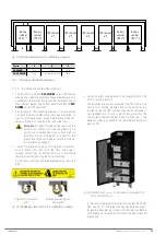
The SLC CUBE4 UPS has the following switches (some are op-
tional, as indicated):
•
Rectifier AC input line switch (common to the bypass line, if it
is not a unit with an optional separate bypass): this switch is a
circuit breaker for models up to 50 kVA, and a disconnect switch
for 80 kVA and higher.
•
AC bypass line switch, optional for units with a circuit
breaker-type separate bypass.
•
Disconnect switch for maintenance bypass. This switch will
remain mechanically locked (against activation) during op-
eration in normal mode.
•
Output circuit breaker switch. It allows the voltage supplied
by the UPS to be connected to the loads, or for them to be
isolated if necessary.
•
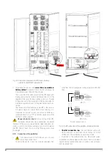
Battery disconnect switch for 50 kVA models and higher.
It allows the UPS to be isolated from the power supply
provided by the batteries, whether they are internal or ex-
ternal. On models of up to 40 kVA, the UPS can be isolated
from the batteries by disconnecting a connector that is
easily accessible by the operator (whether they are internal
Detail A
-
, or external -
In addition, in external battery cabinets, there will be a con-
nection and disconnection method
(Q8)
.
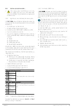
4.6.2. Control panel with touchscreen
The control panel of the UPS is fully integrated into a graphic
touchscreen ("touch panel"). Some of the characteristics of this
screen are as follows:
•
5” diagonal screen size.
•
16:9 aspect ratio.
•
Resolution of 800 x 480 pixels.
•
65 K colours.
•
Capacitive touch sensor.
This control panel allows:
•
Monitoring of measurements and operating parameters.
•
Display and acknowledgement of alarms and statuses (ac-
tive and passed).
•
Modification of basic operating configurations and parameters.
•
Change of UPS operating mode (normal, bypass, ECO mode,
battery test).
4.6.3. External interface and communications
The unit's interface with the outside consists of various dedi-
cated input and output signals, and different ports and com-
munication slots.
1.
Signalling (terminal strip):
Digital inputs (standard unit):
–
Generator set supplying the UPS.
–
Remote stop (“shutdown”).
–
External maintenance bypass auxiliary contact.
–
External output switch auxiliary contact.
–
Emergency stop (EPO).
Digital outputs, via potential free relay contacts
(standard unit):
–
Unit in bypass mode.
–
Unit in battery mode.
–
Battery end of autonomy alarm (early activation).
–
Any alarm present in the unit.
2.
External measurements (terminal strip):
Remote battery temperature (up to 10 m, for greater
distances, dedicated communication slot).
External ambient temperature.
3.
Direct communications of the unit:
USB (Type-B) port: Modbus protocol for user and ser-
vice software for qualified staff.
RS232/RS485 port (DB9 connector): Modbus protocol
for user, physically sharing the same connector (dif-
ferent pins).
Parallel ports (RJ45 connectors): to connect the units in
parallel, it is necessary to interconnect them (output of
one to the input of the next one) using 8-wire cables (4
Ethernet-type pairs).
4.
Communications in slots:
Slot no. 1, “Nimbus Services” (standard unit): a "Nimbus"
communications card is supplied by default, which allows
connection to the "cloud" services owned by SALICRU.
Slot no. 2: A free slot for installing an SNMP card, or
any other card for extending communications, signal-
ling and/or other services.


