38
SALICRU
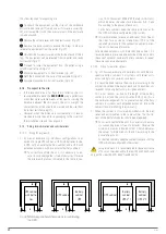
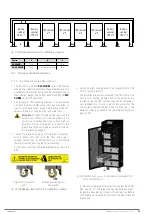
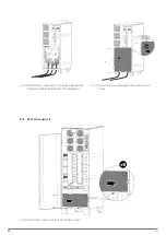
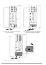
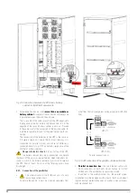
5.2.3. Connection to the mains, input terminals (see
•
As this unit has protection against class I electric
shocks, it is essential to install a protective earth con-
ductor (connect earth (
)). Connect this conductor to the
earth terminal before supplying voltage to the input terminals.
• In accordance with the EN-IEC 62040-1 safety standard, in
units without a static bypass line, the installation must be
equipped with an automatic "Backfeed protection" system,
such as a contactor, which prevents voltage or hazardous
energy from appearing in the UPS input line during a net-
work failure.
The standard is applicable regardless of whether the supply
network is single-phase or three-phase and both for individual
units and for each UPS of a parallel system.
•
In the documentation supplied with this user manual
and/or on your pen drive, the information relating to
the "Recommended installation" is provided. It shows the
wiring diagrams, as well as the protection size and the min-
imum cross-sections of the cables connected to the unit,
according to its nominal working voltage. All values are cal-
culated for total maximum cable length of 30 m between the
distribution board, unit and loads.
For longer lengths, correct the cross-sections to prevent
voltage drops, observing the regulations or standards of
the country.
In the same documentation and for each configuration,
the information for "N" parallel units is available, as well
as the characteristics of the "Backfeed protection".
•
There can be no bypass of the line that runs from
the "Backfeed protection" to the UPS, as this would
not comply with the safety standard.
• Warning labels must be placed on all primary power
switches, installed in areas away from the unit, to alert
electrical maintenance staff to the presence of a UPS in
the circuit.
The label will contain the following or an equivalent text:
Before working on the circuit
Isolate the Uninterruptible Power Supply (UPS).
Check the voltage between all terminals, including
the protective earth terminal.
UPS return voltage risk.
• Connect the input cables to the respective terminals ac-
cording to the configuration of the available unit.
For parallel systems, the connections that go from the
panel to each unit must be repeated.
Connect the R-S-T-N power cables to the input terminals, ob-
serving the order of the phases and neutral indicated on the
unit's labelling and in this manual. If the order of the phases is
not observed, the unit will not work.
When there are discrepancies between the labelling and the
instructions in this manual, the labelling will always prevail.
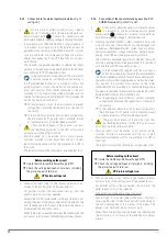
5.2.4. Connection of the separate static bypass line. SLC
.
•
As this unit has protection against class I electric shocks,
it is essential to install a protective earth conductor
(connect earth ( )). Connect this conductor to the earth ter-
minal before supplying voltage to the input terminals.
• Following the EN-IEC 62040-1 safety standard, in units with
a static bypass line, the installation must be equipped with
an automatic "Backfeed protection" system, such as a discon-
nector, which prevents voltage or hazardous energy from ap-
pearing in the UPS input line during a network failure.
The standard is applicable regardless of whether the supply
network is single-phase or three-phase and both for individual
units and for each UPS of a parallel system.
•
In the documentation supplied with this user manual
and/or on your pen drive, there is information relating to
the "Recommended installation" for each input and output con-
figuration. It shows the wiring diagrams, as well as the protec-
tion size and the minimum cross-sections of the cables
connected to the unit, according to its nominal working voltage.
All values are calculated for total maximum cable length of 30 m
between the distribution board, unit and loads.
For longer lengths, correct the cross-sections to prevent
voltage drops, observing the regulations or standards of
the country.
In the same documentation and for each configuration,
the information for "N" parallel units is available, as well
as the characteristics of the "Backfeed protection".
•
There can be no bypass of the line that runs from
the "Backfeed protection" to the UPS, as this would
not comply with the safety standard.
• Warning labels must be placed on all primary power
switches, installed in areas away from the unit, to alert
electrical maintenance staff to the presence of a UPS in
the circuit.
The label will contain the following or an equivalent text:
Before working on the circuit
Isolate the Uninterruptible Power Supply (UPS).
Check the voltage between all terminals, including
the protective earth terminal.
UPS return voltage risk.
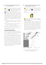
• Connect the bypass input cables to the respective termi-
nals according to the configuration of the available unit.
For parallel systems, the connections that go from the
panel to each unit must be repeated.
Connection to a three-phase bypass network:
Connect the R-S-T-N power cables to the bypass terminals,
observing the order of the phases and neutral indicated on
the unit's labelling and in this manual. If the order of the
phases is not observed, the unit will not work.
When there are discrepancies between the labelling and
the instructions in this manual, the labelling will always
prevail.


