20
SALICRU
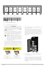
MANUAL BYPASS
RECTIFIER-BOOSTER
DC-LINK
INVERTER
BATTERY
CHARGER
BATTERY PACK
BYPASS
LINE
AC INPUT
AC OUTPUT
BYPASS
STATIC
SWITCH
Fig. 12.
SLC CUBE4 UPS block diagram.
4.4.2. Rectifier-booster
The rectifier-booster has the double function of:
•
Converting (rectify) the alternating voltage (AC) into direct
voltage (DC) in normal mode (input network voltage pre-
sent), voltage required at the inverter input.
•
Adapting (boost) the battery voltage (DC) to the required
direct voltage (DC) at the inverter input.
This direct voltage generated by the rectifier-booster (supplied to
the inverter) will be referred to as direct bus voltage.
The rectifier-booster has a static switch at the input, using
thyristors, which allows the input source, alternate network
or batteries, to be selected at all times, according to the UPS
operating mode.
The rectification-boosting stage is carried out by the 3 sets of
dual boost converters, one per phase, made up of a power in-
ductor, IGBT transistors, diodes and electrolytic capacitors for
filtering the bus voltage. The excitation of the IGBT transis-
tors via PWM, controlled digitally, is carried out by one of the
floating-point DSPs, with the aim of obtaining:
•
Sinusoidal current absorption (low THDi) in normal or AC
mode, so that no distortion is added to the input network,
avoiding affecting the other loads.
•
Power factor 1 from very low levels of output load.
•
Balanced absorption of the three-phase input currents.
•
Direct current absorption in battery or DC mode.
The sizing of the rectifier will allow the inverter to be perma-
nently supplied with 100% load, plus the power required to
charge the batteries.
4.4.3. Inverter
The inverter converts the DC voltage present at the DC bus into
AC alternating voltage, stabilised in amplitude and frequency.
Therefore, it completes the double conversion, so that this new
"clean" AC voltage is independent of the input voltage (isolated
from potential disturbances, peaks, dips, unstable frequency,
etc.).
The architecture of this converter is based on 3 separate single-
phase inverters with 3 switching levels (4 IGBT transistors per
phase), thus achieving the following:
•
Minimal switching losses (half the PWM voltage compared
to a conventional 2-level inverter).
•
A reduction of the switching ripple on the power inductor,
and an overall reduction of the L-C filtering effort.
•
The switching frequency is raised to non-audible values.
The control of this inverter is also digital, and is carried out by
another of the system's floating-point DSP cores. The gener-
ated voltage has:
•
Low harmonic voltage distortion (THDv), even for highly dis-
torting loads (non-linear load).
•
Stable output voltage, with accuracies greater than 0.5%
with regards to voltage and greater than 0.05% with re-
gards to frequency.
•
Current limit: in the event of output short circuits, starting
loads with peak overcurrent ("in-rush"), or similar. The in-
verter limits the output current by reducing the output
voltage (at the limit, to 0 V in the case of short circuits),
in order to protect the unit in such situations, or it allows
"starting" loads with this initial overcurrent.
The inverter is sized to operate permanently loaded at 100%,
and also for temporary overloads, depending on a Load-Time
curve, with typical values of 125% for 10 minutes, 150% for
1 minute.
4.4.4. Batteries and battery charger
The batteries are the element that allows the UPS to work in
the absence of an AC input network, i.e. in autonomy or battery
mode. These elements can be integrated in the standard cab-
inet of the UPS or in an external cabinet or rack (a combination
of internal and external batteries is also an option). The number
of batteries (normally in 12 V blocks) must be enough to allow
the rectifier-booster to work within its operating ranges, with a
certain amount of flexibility to adjust to the required autonomy.
As already explained in the Rectifier-booster section, in battery
mode, the battery voltage will be connected (via controlled thy-


