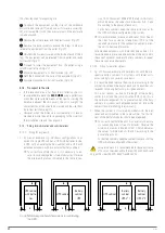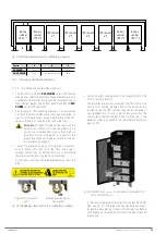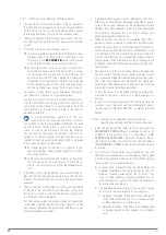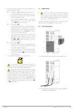
35
• As a result of the battery layout, the respective protection
will be arranged as follows:
Units from group
"
a
"
indicated in the previous point.
–
For 30 kVA and 40 kVA units, the internal battery pro-
tection consists of internal fuses located in the UPS
and not accessible to the user.
–
For 50 kVA, 60 kVA and 80 kVA units, the internal
battery protection consists of a disconnect switch
+ fuses
(Q6)
(see
and Fig. 6
Units from group
"
b.1
.".
–
For 30 kVA and 40 kVA units, the internal battery
protection consists of internal fuses that are not
accessible to the user and disconnect terminals for
external batteries (see
Detail B
- and Fig. 3
), all located in the UPS.
–
For 50, kVA, 60 kVA and 80 kVA units, the internal
and external battery protection consists of both
disconnect switches located on the front of the
UPS
(Q6)
or
(Q3)
, respectively (see
), and internal fuses.
Units from group
"
b.2.
"
.
–
For 30 kVA and 40 kVA units, the external battery
protection consists of disconnect terminals located
in the UPS (see
).
–
For 50 kVA, 60 kVA and 80 kVA units, the external
battery protection consists of disconnect switch
on the front of the UPS
(Q3)
(see
),
and internal fuses.
• The original factory battery circuit type is open.
–
+
•
Do not handle the battery connectors and/or the
disconnect switch when the unit is running. These
mechanisms cannot be disconnected under load.
•
When the unit or parallel system's power supply
fails beyond a simple intervention and it is expected
to be out of service for a prolonged period, first shut it
down completely and then disconnect the batteries. For 30
kVA and 40 kVA units, disconnect the internal batteries
located on the front of the unit (see
Detail A
). For 50
kVA, 60 kVA and 80 kVA units, and for external battery
cabinets, open the corresponding disconnect switch (
Q3
and
Q8
, respectively).
5.2. CONNECTIONS
•
This unit is suitable for installation in networks
with a TT, TN-S, TN-C or IT power distribution
system, taking into account the specificities of the system
used and the national electrical regulations of the destina-
tion country at the time of installation.
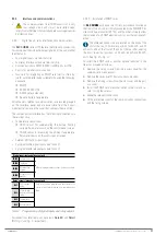
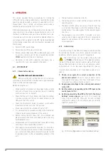
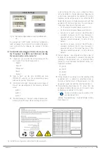
The following Fig. 39 to Fig. 46 show the I / O and Bypass con-
nection procedure independent of the equipment.
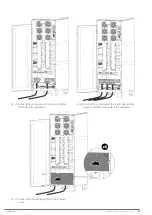
5.2.1. 30-40 kVA equipments.
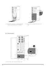
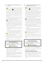
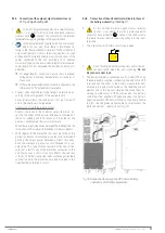
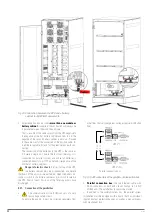
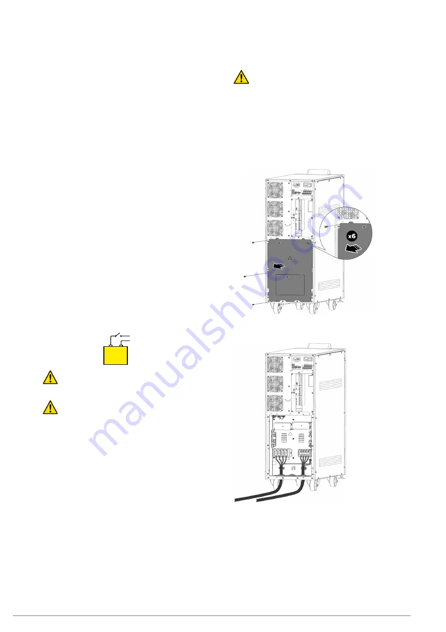
Fig. 40.
Detail of the removal of the rear terminal cover.
Fig. 41.
Detail of the connection of the Input and Output
terminals of the equipment.
SLC CUBE4
- UNINTERRUPTIBLE POWER SUPPLY SYSTEM
-
USER MANUAL


