47
6.3. MANUAL OR MAINTENANCE BYPASS
When a repair or maintenance intervention on the UPS is nec-
essary, to be carried out by the qualified Technical Service, and
the continuity of supply to the loads must be maintained, the
output must be transferred to the bypass line via the mainte-
nance bypass switch
(Q5)
, integrated in the unit or optionally in
the external control panel (with the auxiliary contact correctly
wired to the UPS interface terminals).
6.3.1. Transferring to maintenance bypass mode
To detail this procedure, we will start from the initial point of
the UPS operating in normal mode (rectifier converters, charger
and inverter running; output in inverter). If it is necessary to
transfer to maintenance bypass from another status (from by-
pass mode, for example, either by manual transfer or by unit
alarm), carry out the same steps, for greater safety.
Do not actuate the manual bypass switch (of the
unit or on the external control panel) directly in
normal mode, or in general, without strictly following the
procedure described here. The "uncontrolled" operation
of this mechanism may cause faults on the unit and/or
damage to the installation.
To switch to maintenance bypass mode:
1.
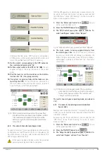
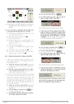
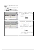
Press the "Status and Control" icon
You are
on the screen described in
.
2.
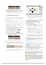
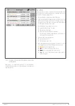
Press the "Start/Stop UPS" icon
3.
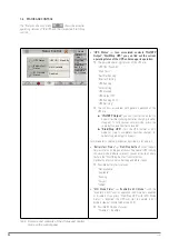
The "UPS Control" pop-up box appears, with the "Start"
and "Stop" options. Press "Stop".
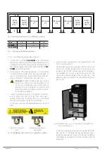
Fig. 60.
"UPS Control" pop-up window. Press "Stop".
4.
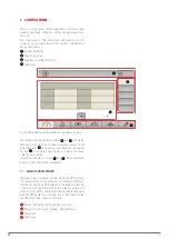
The loads switch to being supplied directly from the
static bypass line
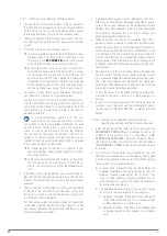
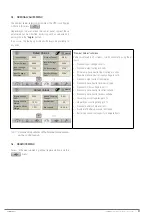
. A new "UPS Unit on Bypass" alarm ap-
pears, warning us of the current "risk" situation for critical
loads. Also check that the unit's synoptic corresponds to
(UPS stopped).
5.
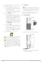
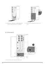
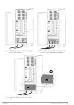
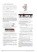
Remove the mechanical lock of the UPS manual by-
pass switch
: unscrew the screws provided and remove the
6.
Set the manual bypass switch of the UPS to "On" (
Q5
).
7.
Remove the mechanical lock of the manual bypass
switch on the external control panel.
8.
Set the manual bypass switch of the external control
panel to "On".
9.
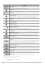
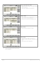
The unit reports the current status via the "Mainten.
Byp Closed" alarm (maintenance bypass switch
closed).
R S T N
R S T N
U V
W
N
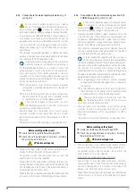
Fig. 61.
Mechanical lock of the UPS maintenance bypass
switch, 30 kVA and 40 kVA units.
AC OUTPUT
BATTERY
AC INPUT
MAINTENANCE
BYPASS
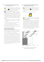
Fig. 62.
Mechanical lock of the UPS maintenance bypass
switch, 50 kVA, 60 kVA and 80 kVA units.
10.
Set the switch corresponding to the UPS output on
the control panel (external) to "Off".
11.
Set the output switch of the UPS to "Off" (
Q2
).
12.
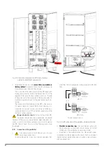
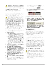
Disconnect the batteries:
a.
Units with internal batteries
: disconnect the 3-pole
Detail A
, on the front), or set
the battery switch to "Off" (
Q6
, on the front), as appli-
cable.
b.
Units with external batteries
: disconnect the battery
circuit breaker on 50 kVA, 60 kVA and 80 kVA units (
Q3
,
on the front), or disconnect the external battery cables on
the back of 30 kVA and 40 kVA units, as applicable. Also,
set the external battery cabinet switch to "Off"
(Q8)
.
c.
Units with shared internal and external batteries:
carry out points
a.
and
b.
described above one after
the other.
13.
Set the switch corresponding to the UPS input on the
control panel (external) to "Off".
If there is a separate
bypass line for the UPS, also set this switch on the control
panel to "Off".
At this point, the unit will stop completely
(the control
panel screen switches off).
14.
Set the input switch of the UPS to "Off" (
Q1
).
15.
In units with a separate static bypass input, set the
corresponding bypass switch to "Off" (
Q4
).
The unit is now in maintenance bypass operating mode,
described in
DANGER OF ELECTRIC SHOCK: before any repair
or maintenance operation inside the unit, to be
carried out solely and exclusively by the qualified Tech-
nical Service, wait for approximately 5 minutes from this
moment, the required time for the electrolytic capacitors
to discharge.
SLC CUBE4
- UNINTERRUPTIBLE POWER SUPPLY SYSTEM
-
USER MANUAL

