


23
XL-SA20018UM-en-US Rev H · 2017-12-14 · Amendments and Errors Reserved · © SAF-HOLLAND, Inc., SAF-HOLLAND, HOLLAND, SAF, and logos are trademarks of
SAF-HOLLAND S.A., SAF-HOLLAND GmbH, and SAF-HOLLAND, Inc.
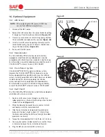
ABS Sensor Replacement
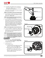
Figure 40
SENSOR
HOLDER
RETAINING
SPRING CLIP
ABS SENSOR
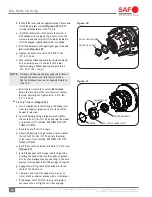
Figure 41
DUST SHIELD
CLAMP
BAND
UP-TURNED TAB
CLAMP BAND
BOLT
AXLE
16. Optional Equipment
16.1 ABS Sensor
NOTE:
When replacing the ABS sensor, DO NOT mix
sensors from different manufacturers.
1. Disconnect the ABS sensor.
2. Remove the ABS sensor from the sensor holder by pulling
it straight out from the holder and discard
(Figure 40).
3. If necessary, remove the sensor retaining spring clip from
the sensor holder and replace with a new clip.
(Figure 40).
4. Install a new ABS sensor by pushing it directly into the
sensor holder/spring clip until it contacts the ABS toner
ring in the hub assembly
(Figure 40).
5. Re-connect the ABS sensor.
16.2 Hubodometer
The SAF-HOLLAND
®
P89 disc brake axle can be factory
equipped or retrofitted with any hubodometer currently
compatible with a North American standard six bolt hub cap.
For information on specific hubodometer availability, contact
SAF-HOLLAND
®
Customer Service at 888-396-6501.
16.3 Tire Inflation System
SAF-HOLLAND
®
DOES NOT supply tire inflation systems.
However, the SAF-HOLLAND
®
P89 disc brake axle can be
factory equipped to be compatible with many tire inflation
systems currently compatible with a North American standard
six bolt hub cap. This includes providing tire inflation
system hubcaps that are compatible with hubodometers.
For information on specific Tire Inflation fitting availability,
contact SAF-HOLLAND
®
Customer Service at 888-396-6501.
16.4 Dust Shield
The SAF-HOLLAND
®
P89 disc brake can be factory equipped or
retrofitted with a disc dust shield.
1. Route any ABS sensor wires through one of the two
rubber grommets on the dust shield and position the dust
shield on the axle.
(Figure 41)
.
2. Wrap the clamp band around the axle and dust shield
and loosely install the clamp band bolt.
3. Slide the dust shield and clamp band toward the disc
brake until the dust shield is about 1/2
"
(12mm) from
the brake rotor, pulling the ABS wire through the rubber
grommet as necessary.
4. Torque the clamp band bolt to 20-25 ft.-lbs. (27-34 N•m).
5. Use a pry bar and/or a rubber mallet to ensure that there
is clearance between the dust shield and the rotor.
6. Plug the ABS sensor into the ABS system wire.