


10
XL-SA20018UM-en-US Rev H · 2017-12-14 · Amendments and Errors Reserved · © SAF-HOLLAND, Inc., SAF-HOLLAND, HOLLAND, SAF, and logos are trademarks of
SAF-HOLLAND S.A., SAF-HOLLAND GmbH, and SAF-HOLLAND, Inc.
Caliper Identification and Inspection
6.2 Rotor Wear Inspection
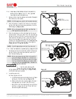
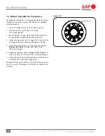
1. Carefully inspect both sides of the brake rotor friction
surface
(Figure 9).
a. Spider web cracking is acceptable
(Area A)
.
b. Radial cracks less than 0.06" (1.5 mm) deep or wide
with lengths less than 75% of the width of the rotor
friction surface
(Area B)
are acceptable.
c. Grooves in the rotor surface are acceptable only if
they are less than 0.06" (1.5 mm) deep
(Area C)
.
d. Cracks that run completely to either edge of the hub
are NOT acceptable, regardless of depth
(Area D)
.
2. Measure the brake rotor thickness and re-surface, if
necessary. For proper brake function, the minimum
thickness for re-surfacing the brake rotor is defined as
1.54" (39 mm).
Re-surfacing the brake rotor beyond
the minimum thickness could cause
component failure which, if not avoided,
could result in death or serious injury.
IMPORTANT:
DO NOT use high-pressure cleaners or
liquid cleaners on the brake rotor.
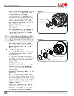
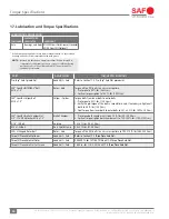
If the overall wear limits for the brake rotor or brake pads are
exceeded
(Figure 10)
, the rotor and pads MUST be replaced.
Refer to rotor replacement instructions as detailed in Section
9. For brake pad replacement, refer to caliper instruction
manuals identified in Section 5.
For both the inner and outer pads, the maximum brake pad
wear difference is 0.2" (5.0 mm).
Failure to replace brake rotor and pads
when minimum wear limits are reached
could cause component failure which,
if not avoided, could result in death or
serious injury.
NOTE:
When replacing the brake pads or brake rotor, use
only Original SAF-HOLLAND
®
rotors and approved
brake pads.
IMPORTANT:
When replacing worn brake pads, ALL pads
on the axle MUST be replaced.
NOTE:
During brake repairs, conduct a visual inspection of
the seals on the brake caliper. Refer to Section 6.3
for more information.
BRAKE ROTOR
BRAKE PAD
DIAMETER “A” NEW
“B”
WEAR LIMIT “C” NEW
“D”
WEAR LIMIT
430 mm
45 mm
37 mm
23 mm
2 mm
16.93"
1.77"
1.46"
1.18"
0.08"
Figure 10
"A"
NEW
ROTOR
"B"
WORN
ROTOR
"C"
NEW PAD
"D"
WORN
PAD
Figure 9
0.06" (1.5 MM)
MAX. DEPTH
AREA A
ROTOR
FRICTION
SURFACE
AREA B
75%
OF
ROTOR
WIDTH
AREA C
AREA C
CROSS SECTION VIEW
AREA D