


14
XL-SA20018UM-en-US Rev H · 2017-12-14 · Amendments and Errors Reserved · © SAF-HOLLAND, Inc., SAF-HOLLAND, HOLLAND, SAF, and logos are trademarks of
SAF-HOLLAND S.A., SAF-HOLLAND GmbH, and SAF-HOLLAND, Inc.
Disc Brake Servicing
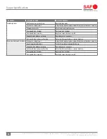
4. Clean the rotor contact surface on the hub. Using
compressed air, clean the tapped holes in the hub. Check
to make sure the threads are undamaged.
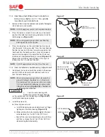
5. Attach the new rotor to the hub using ten (10) new SAF
®
specific INTEGRAL
®
bolts and washers
(Figure 18)
.
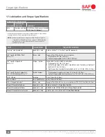
Using a torque wrench, pre-torque the bolts to 40 ft.-lbs.
(54 N•m). For final torque, tighten the bolts to 140 ft.-lbs.
(190 N•m) using a crisscross pattern. Refer to the Torque
Chart in Section 17 for more information.
IMPORTANT:
When attaching a new rotor to the head
unit, use only new SAF
®
specified connection
bolts. Bolts MUST be clean and free from
oil and grease.
Failure to use only SAF
®
specified connection
bolts could cause component failure which,
if not avoided, could result in death or
serious injury.
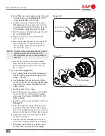
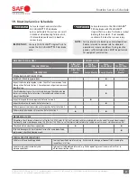
When installing new washers, the
attachment bolts can interfere with the
ABS sensor block. Ensure that there is
clearance provided for ABS Sensor Block
(Figure 19)
. Failure to provide clearance
can cause damage to property. Refer to
service bulletin XL-SA20031SB-en-US
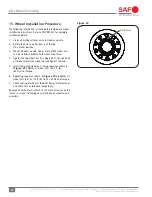
9.2 U-Shaped Rotor
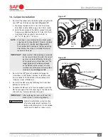
1. Remove the ABS sensor by following the instructions
detailed in Section 16.1.
2. Remove the head unit, Refer to Section 6 instructions.
3. Remove the rotor from the hub using a size 15/16"
socket. Loosen and discard all ten (10) connection bolts
and washers.
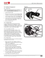
4. Clean the rotor contact surface on the hub. Using
compressed air, clean the tapped holes in the hub. Check
to make sure the threads are undamaged.
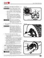
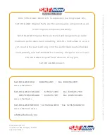
5. Attach the new rotor using ten (10) new bolts and washers
supplied in the rotor kit
(Figure 20)
. Using a torque wrench,
tighten the bolts to 190 to 210 ft.-Lbs. (260-285 N•m).
IMPORTANT:
When attaching a new rotor to the hub,
use only SAF
®
specified connection bolts
and washers. Bolts MUST be clean and free
from oil and grease.
Failure to use only SAF
®
specified
connection bolts and washers could cause
component failure which, if not avoided,
could result in death or serious injury.
Figure 18
Figure 19
Figure 20
ROTOR
WASHERS
HEAD UNIT
BOLTS
CONNECTION BOLTS
ABS SENSOR BLOCK
MODIFIED ABS
SENSOR BLOCK
3/16" CHAMFER