


13
XL-SA20018UM-en-US Rev H · 2017-12-14 · Amendments and Errors Reserved · © SAF-HOLLAND, Inc., SAF-HOLLAND, HOLLAND, SAF, and logos are trademarks of
SAF-HOLLAND S.A., SAF-HOLLAND GmbH, and SAF-HOLLAND, Inc.
Disc Brake Servicing
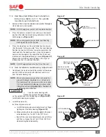
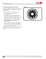
12. Remove the inner hub bearing from the spindle or from
the inside of the hub
(Figure 17)
.
13. The spindle mount hub seal can be driven off the spindle
by striking the ring from the back side or prying off with
a crow’s foot bar. Be careful not to gouge the spindle
shoulder. Discard the used seal. A new seal is required
when re-assembled
(Figure 17)
.
DO NOT use a chisel to cut the seal. The
shoulder can be damaged, resulting in a
leak which, if not avoided, could lead to
wheel end and/or brake failure.
8. Bearing Inspection
Thoroughly clean bearings. DO NOT mix
a synthetic base grease or oil with an
organic/mineral base lubricant.
DO NOT dry hub bearings with compressed
air. Bearing damage could result.
1. After removing the head unit, clean excess grease from
the bearings.
IMPORTANT:
A bearing which has been removed from a
vehicle should be cleaned with solvent. NEVER
use steam or water which will rust bearings.
IMPORTANT:
Bearings that are rusted, flaked, pitted, or
have damaged cages should be replaced. It
is recommended to replace all questionable
bearings and ALWAYS replace the cup and
cone as a matched set.
IMPORTANT:
NEVER re-assemble a tapered roller bearing
in a damaged or worn bearing cup or spindle.
Bearing cup or spindle should be replaced
and NOT re-machined if damaged or worn.
9. Rotor Replacement
Failure to follow these instructions could
cause component failure which, if not avoided,
could result in death or serious injury.
9.1 INTEGRAL
®
Rotor
Refer to pages 6 and 7 for Integral and U-Shaped
Identification. See Section 9.2 for U-Shaped Rotor.
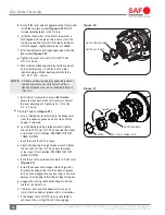
1. Remove the ABS sensor by following the instructions
detailed in Section 16.1.
2. Remove the hub, refer to Section 6 instructions.
3. Remove the rotor from the hub using a size 15 mm
socket to loosen and discard all ten (10) connection bolts
(Figure 18)
.
Figure 17
HUB SEAL
INNER HUB
BEARING