


18
XL-SA20018UM-en-US Rev H · 2017-12-14 · Amendments and Errors Reserved · © SAF-HOLLAND, Inc., SAF-HOLLAND, HOLLAND, SAF, and logos are trademarks of
SAF-HOLLAND S.A., SAF-HOLLAND GmbH, and SAF-HOLLAND, Inc.
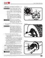
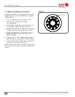
Figure 31
OUTER BEARING
RAISED MARK
PRO-TORQ
®
WHEEL NUT
KEEPER
Disc Brake Servicing
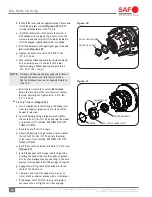
d. Back off the inner axle nut approximately 1/4 turn and
install the axle lock washer
(Figure 30)
. DO NOT
include socket backlash in the 1/4 turn.
e. Install the lock washer. If the hole in the washer is
NOT aligned with the pin on the inner nut, turn the
washer around and re-install. If the pin and hole are
still NOT aligned, slightly adjust parts as needed.
f. Install the outer axle nut finger tight against the axle
lock washer
(Figure 30)
.
g. Tighten the outer axle nut to 200-300 ft.-lbs.
(271-407 N•m).
h. Measure wheel bearing end play (distance wheel
end assembly moves in and out) with a dial
indicator gauge. Wheel bearing end play to be
.001-.005" (.03- .13mm).
NOTE:
if wheel end bearing end play needs adjustment,
remove the outer nut and lock washer, then
tighten or loosen inner nut as needed. Return to
step "6.e".
i. Install the set screw into an accessible threaded
hole in the lock washer. The set screw must contact
the inner adjusting nut. Tighten to 16 - 20 in.-lbs.
(1.8 - 2.2 N•m).
Pro-Torq
®
axle nut
(Figure 31)
:
a. Use a screwdriver to carefully pry the keeper arm
from the undercut groove on each side until the
keeper is released.
b. Seat the bearing. Using a torque wrench, tighten
the nut to 200 ft.-lbs. (271 N•m) and spin the wheel
at least one (1) full rotation. PERFORM THIS STEP
THREE (3)TIMES.
c. Back the nut off until it is loose.
d. Adjust the bearing. Using a torque wrench, tighten
the nut to 100 ft.-lbs. (137 N•m). Spin the wheel
at least one (1) full rotation. PERFORM THIS STEP
THREE (3) TIMES.
e. Back the nut off one raised face mark (1/8 of a turn)
(Figure 31)
.
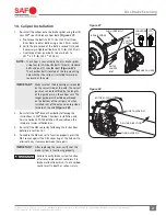
f. Install the keeper with orange side facing out by
inserting the keeper tab into the undercut groove
of the nut and engage the keyway tang in the axle
keyway. Insert keeper tab with bent legs facing out.
g. Engage the mating teeth of the keeper with the
teeth of the wheel nut.
h. Compress and insert the keeper arms, one at a
time, into the undercut groove with a screwdriver.
i. If the keeper teeth DO NOT line up with teeth in
nut, loosen the nut slightly until they engage.
Figure 30
AXLE LOCK WASHER
OUTER AXLE NUT