


11
XL-SA20018UM-en-US Rev H · 2017-12-14 · Amendments and Errors Reserved · © SAF-HOLLAND, Inc., SAF-HOLLAND, HOLLAND, SAF, and logos are trademarks of
SAF-HOLLAND S.A., SAF-HOLLAND GmbH, and SAF-HOLLAND, Inc.
Disc Brake Servicing
7. Hub, Bearing and Seal Removal
NOTE:
Before beginning any axle/brake service procedures,
park the vehicle on a level surface. Block the wheels
to prevent the vehicle from moving. Support the
vehicle and axles(s) with safety stands. DO NOT
work under a vehicle supported only by jacks.
Jacks can slip or fall over. Serious personal injury
and damage to components can result.
Failure to properly support the vehicle
and axles prior to commencing work could
create a crush hazard which, if not avoided,
could result in death or serious injury.
1. Release the trailer brakes, and cage the spring brakes
according to the spring brake manufacturer’s instructions.
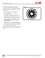
Remove the tire and wheel assembly to access hub
and rotor.
2. Remove wheels from hub using support device such as a
wheel dolly.
Failure to support weight during installation
or removal of wheels could create a crush
hazard which, if not avoided, could result
in minor to moderate injury.
3. Remove the ABS sensor by following the instructions
detailed in Section 16.1.
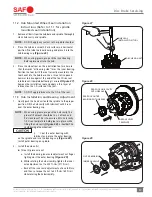
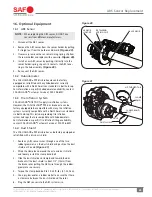
4. Detach the brake chamber from the brake caliper by
loosening and removing the two (2) mounting nuts
(Figure 11)
.
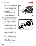
5. Remove the brake caliper from the brake spider by using
a size 24 mm socket to loosen. Discard all four (4) brake
caliper bolts
(Figure 12)
.
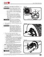
6. With a 1/2" socket, remove the six (6) hub cap bolts and
the hub cap
(Figure 13)
.
NOTE:
Be prepared to collect lubrication fluid when
removing hub cap.
Figure 12
Figure 11
MOUNTING NUTS (2)
BRAKE CHAMBER
BRAKE CALIPER
BOLTS (4)
BRAKE SPIDER
BRAKE CALIPER
Figure 13
HUB CAP GASKET
HUB CAP
HUB CAP
BOLTS (6)