


RDC6445GT5 Laser cutting system hardware user manualV1.1
深圳市睿达科技有限公司
40
2.Input the coordinates that need to be set as the positioning point in the edit box for the positioning
point X(mm), and positioning point Y(mm). If user not sure whether the input coordinates are the
position you want, click the “Move to Positioning Point” button, and the machine will automatically
move to the current input coordinate position. Then click the “Set as Positioning Point” button, the
status of the positioning point button becomes selected and enabled
, and when the enabled
“Positioning Point” button is selected, text description of the button “Set as Positioning Point” changes
to “Cancel Positioning Point” as shown in Figure 8.5.1-4.
3.If the coordinates of the positioning point that has been enabled need to be set,user need to click
“Cancel Positioning Point” first, and then set repeat operation 2.
Set by the axis moving:
Figure 8.5.1-6
1.Select the positioning point button to be set, the positioning point 1 is selected in the figure.
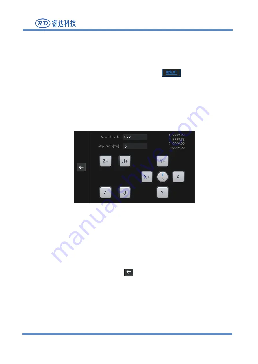
2.Click the finger button in the upper right corner of Figure 8.5.1-3 to enter the axis operation interface,
as shown in Figure 8.5.1-5. Observe the position of the machine laser head through the motion shaft.
When it is the position you need, click the button
on the left to return to the upper-level interface,
and then click “Set Positioning Point” to set it successfully.
3.If the coordinates of the positioning point that has been enabled need to be set, user need to click
“Cancel Positioning Point” first, and then set repeat operation 2.
Each sub-item is introduced as follows:
Multi-positioning point enable: “Yes” and “No” are optional. When “No” is selected,


