LaserCuttistV1.2 Laser Cutting system
RuiDa Technology E-Mail:
1TH FLOOR,5TH BUILDING,NANYOU
TIANAN INDUSTRIAL ZONE,SHENZHEN
Web:
www.rd-acs.com
Phone: (086)0755-26066687
FAX: 0755-2698287
12
Step 5
:
connect X
、
Y axis motor
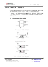
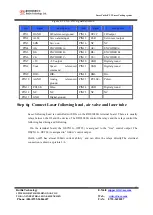
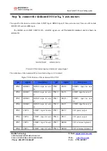
There are 4 channels for motor control. This interface is DB25. The signals in the interface include
pulse+dir, alarm ,servo on and encoder signals. Figure 3 is the definition of the signals.
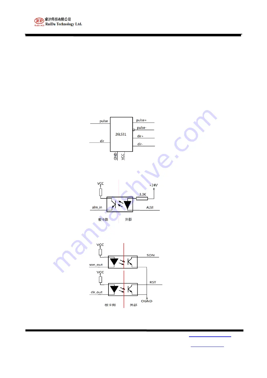
The step or servo motor signals are in
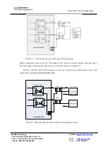
Differential
style. Shown in the picture 2-3. Alarm
signal is
photoelectric isolation. The connection between RDS3040G and motors is described in
detail in appendix 1.
Motor control signals output
Picture 2-3 pulse+dir
Differential output
Picture 2-4 Alarm signal input
Picture 2-5 Servo on and Reset signal output

