background image


       LaserCuttistV1.2 Laser Cutting system


RuiDa Technology                                              E-Mail: 

[email protected]


1TH FLOOR,5TH BUILDING,NANYOU   
TIANAN INDUSTRIAL ZONE,SHENZHEN

                              Web:   

www.rd-acs.com


Phone: (086)0755-26066687


FAX:   0755-2698287


57 


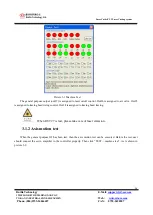
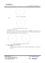
             Picture 3-10    Return to point after cutting 

Click 

  can set the stop point to anywhere on the cut area. If user wishes that the laser head return to the stop 

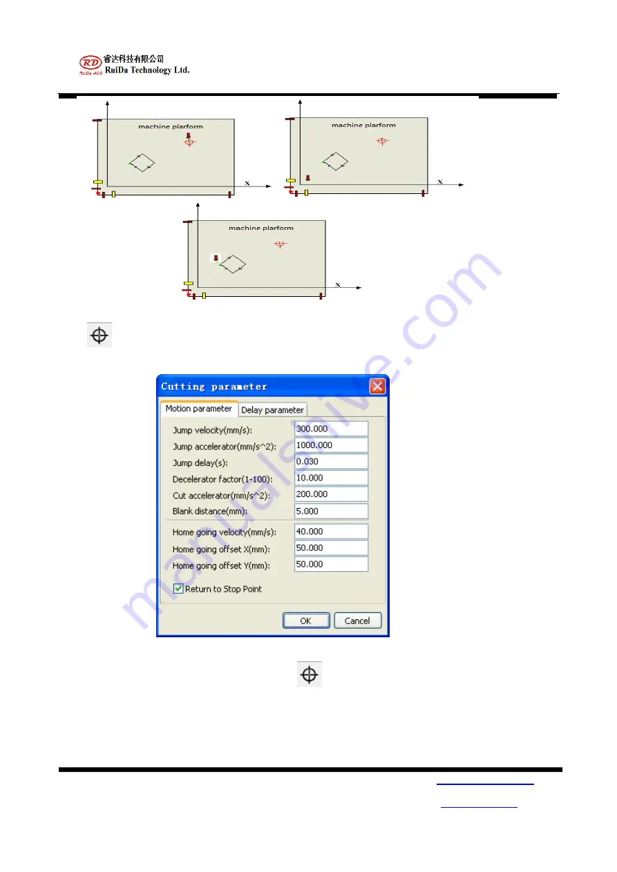
point when finish cutting, the option “return to stop point” should be selected. Shown as picture 3-11. 


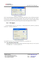
       Picture 3-11 stop point select 

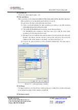
To set the stop point in the cut area, you should click

, and then a dialog will appeared as shown in picture 

3-12. 

Summary of Contents for LaserCuttist V1.2

Page 1: ...086 0755 26066687 FAX 0755 2698287 1 Laser metal cutting system LaserCuttist V1 2 RuiDa Technology Co Ltd Addr 1TH FLOOR 5TH BUILDING NANYOU TIANAN INDUSTRIAL ZONE SHENZHEN Tel 0755 26066687 Fax 0755...

Page 2: ...shed for the customers of RuiDa Laser control Systems Inc Other uses are unauthorized without written permission of Delta Tau Data Systems Inc Clarification 2 Information contained in this manual may...

Page 3: ...6 Chapter 2 installation 7 2 1 PRODUCT LIST 7 2 2 PRODUCT INSTRUCTION 7 2 3 SYSTEMS INSTALLATION AND OPERATION 9 Volum 2 SoftWare Opertion 15 CHAPTER 1 SOFTWARE INSTALLATION 16 CHAPTER 2 SOFTWARE INTR...

Page 4: ...40 3 2 1 SET UP COORDINATION 41 3 2 2 IMPORT A DATA FILE 45 3 2 3 PARAMETERS CONFIG 47 3 2 4 SIMULATION 51 3 2 5 PROCESSING TECHNIC 51 3 3 INFORMATION DISPLAY 60 3 4 OPERATION BOX 60 3 5 TEACHING 61 A...

Page 5: ...Laser Cutting system RuiDa Technology E Mail support rd acs com 1TH FLOOR 5TH BUILDING NANYOU TIANAN INDUSTRIAL ZONE SHENZHEN Web www rd acs com Phone 086 0755 26066687 FAX 0755 2698287 5 Volume 1 El...

Page 6: ...er control This laser cutting system can interfaces with YAG tube and Fiber tube And still has the laser spray nozzle following system interface Servo motor and step motor can connect to RDS3040G moti...

Page 7: ...t switch Y Limit switch Y X Y X STOP START CN12 SHOT AIR RISE TRACE Operation pannel PANASONNIC SERVO MOTOR DRIVER X U V W ENCODER CN2 PIN1 PIN2 PIN3 PIN18 PIN17 PIN4 PIN5 PIN19 PIN6 PIN10 PIN9 PIN22...

Page 8: ...ts that could cause harm to the controller by damaging components or causing electrical shorts When our products are used in an industrial environment install them into an industrial electrical cabine...

Page 9: ...7 9 Picture 2 1 Diagram of RDS3040G PCI Figure 2 1 Encoder Switch SWT1 default status pin status 1 OFF 2 OFF 3 OFF 4 OFF 5 OFF 6 OFF J2 extend interface J1 extend interface JP101 extend interface JP13...

Page 10: ...CI The function of each connector is described in figure2 2 Figure2 2 Connector definition Connector Description CN0 Connect with RDS3040G PCI CN2 X axis motor interface CN3 Y axis motor interface CN4...

Page 11: ...riving ability If 24V power is switched on Then the led in the terminal board will on If there is one or all of the led is not on there are fault in the terminal board Please contact the RuiDa technol...

Page 12: ...ace is DB25 The signals in the interface include pulse dir alarm servo on and encoder signals Figure 3 is the definition of the signals The step or servo motor signals are in Differential style Shown...

Page 13: ...IN8 Vout Speed referenced command PIN21 GND Digital ground PIN9 DIR DIR PIN22 DIR Dir PIN10 AGND Analog referenced ground PIN23 PULSE Pulse PIN11 PULSE Pulse PIN24 GND Digital ground PIN12 NC NC PIN25...

Page 14: ...off This output is OC output It still can directly drive the relays Then the relays control the laser tube laser on or off This is shown in picture 2 7 OUT26 OUT22 OUT23 are assigned to air valve Thes...

Page 15: ...put and dedicated output signal The definition of the dedicated IO is described in Figure 2 8 in detail Figure 2 8 Definition of the dedicated IO in CN11 pin signal description pin signal description...

Page 16: ...rCuttistV1 2 Laser Cutting system RuiDa Technology E Mail support rd acs com 1TH FLOOR 5TH BUILDING NANYOU TIANAN INDUSTRIAL ZONE SHENZHEN Web www rd acs com Phone 086 0755 26066687 FAX 0755 2698287 1...

Page 17: ...Laser Cutting system RuiDa Technology E Mail support rd acs com 1TH FLOOR 5TH BUILDING NANYOU TIANAN INDUSTRIAL ZONE SHENZHEN Web www rd acs com Phone 086 0755 26066687 FAX 0755 2698287 17 Volume 2 O...

Page 18: ...HEN Web www rd acs com Phone 086 0755 26066687 FAX 0755 2698287 18 Chapter 1 software installation Double click the RDMCSetup exe The software will be installed in you computer Please follow the step...

Page 19: ...m 1TH FLOOR 5TH BUILDING NANYOU TIANAN INDUSTRIAL ZONE SHENZHEN Web www rd acs com Phone 086 0755 26066687 FAX 0755 2698287 19 Click next The dialog will tell you to set up shortcut or not Select next...

Page 20: ...AN INDUSTRIAL ZONE SHENZHEN Web www rd acs com Phone 086 0755 26066687 FAX 0755 2698287 20 When the install process has been accomplished You can open the readme txt or not Click finish The LaserCutti...

Page 21: ...SHENZHEN Web www rd acs com Phone 086 0755 26066687 FAX 0755 2698287 21 Chapter 1 Introduction of Lasercuttist 2 1 Mainframe of LaserCuttist The mainframe of the lasercuttist is shown as picture 2 1 P...

Page 22: ...lines Merge joined lines Outline compensation Processing Preview 6 Modify Tools Path optimization sequencing manually internal mold and external mold introducing pin in out lines bridges re orientati...

Page 23: ...en the file with extension rlc can be only opened The rlc file is generated by lasercuttist itself 3 Save and Save as File can be saved as rlc with save or save as operation The rlc file is not only i...

Page 24: ...and vertical mirror rotate array delete the curve selected Only If you have selected the curves Generating Parallel lines Force close lines delete Overlapping lines Merge joined lines Outline compensa...

Page 25: ...ate the parallel lines the dialog is opened You can set the offset length Before you set offset length You should select the Zoom in or Zoom out based on the outline of the graphic element Picture 2 8...

Page 26: ...he overlapping lines 9 Merge intersect When some polygon lines of a closed curve are not connect with each other the merge polygon lines function can made the lines connect with each other Before that...

Page 27: ...de of offset Proportion 1 Draw tools The draw tools is shown as picture 2 13 Picture2 13 Draw tools a Move selected Click and then select the curves in the display window the curves selected can be mo...

Page 28: ...2 14 Transformation parameters To change the position of the curve center can change the position of the curve displayed on the window The width and the height of the curve can still be changed When t...

Page 29: ...ing down the left key of the mouse 3 View selected Pressing down the left key of the mouse and select a rectangle area then release the left key of the mouse The rectangle area will be zoomed in to di...

Page 30: ...hen the password you entered has been authorized the dialog will be opened as picture 2 17 Picture 2 17 machine pareameter 1 Direction polar You can change the direction of the axis motion when you se...

Page 31: ...he quality of the pulse when axis move 1 millimeter 6 Cut range Set the cut range according to the machine work area The cut range is usually smaller than the machine work area 7 Maximum velocity The...

Page 32: ...ance of the grid in the display window can be set 3 Move distance User can use the up key down key to move the select curve to move up and down The unit is set in the adjust distance column User can u...

Page 33: ...mp Acceleration moving acceleration without laser emits c Jump delay Delay for a period of time to wait for the movement to stop d Look ahead coefficient affect the velocity when laser head turn aroun...

Page 34: ...g status The moving down time is the trace delay The delay must be sure that the laser head can move close to the metal plane c Open blowing delay the time that from Switching on the air valve and the...

Page 35: ...t parameter 1 PLT import dpi When a PLT file is imported the parameter should be set The default is 1016 DPI 2 DXF data unit DXF file data unit that described in mm cm 3 Import text information or not...

Page 36: ...ically If the block handle is selected you should set the block height After that you can set the direction of the optimization Lasercuttist will follow the rules to optimize path When you select the...

Page 37: ...too You can use the cursor to click on the curve element The element s name will be displayed in the right bar Using can add the selected left curve element to the right bar Using can add all the cur...

Page 38: ...uter mold manually You can still select the auto mold If you select the auto mold lasercuttist will set all the curve elements to be inner mold or outer mold 4 Automatically add introducing line Befor...

Page 39: ...ld 6 Edit introducing line When you want to modify the pin in out line click the tool Then a cross will display on the cursor That means the operation is in the pin in out modify status User can left...

Page 40: ...e manually 1 Generate with interval length When lasercuttist has been in the adding bridge status you can generate bridges on the curve with the interval length 2 Generate by number When lasercuttist...

Page 41: ...ts in the display window It can display the number of the selected curve elements and the cut path length cut area cut ratio of selected elements Cut path length is the length of the path that needs t...

Page 42: ...there are overlapping lasercuttist will delete the overlapping lines Notice this operation will made a closed curve to be a un closed curve 10 Cut simulation There is a simulation if the cutting proc...

Page 43: ...set any point in the machine cut plane to be the orientation point Moving the laser head to any location and click the orientate point option Then the point is set to be the orientation point When you...

Page 44: ...31 Machine Test User can test the machine motion for the first step With this function the negative and positive direction of the X Y axis can be indentified The limit switch is triggered or not can...

Page 45: ...5 26066687 FAX 0755 2698287 45 2 2 8 Menu Check Shown as picture 2 31 Picture 2 31 Check option 2 2 9 Menu Help Shown as picture 2 32 Picture2 32 Help option 2 3 System work window Just shown as pictu...

Page 46: ...m work window 1 Work information To display the machine coordinate position and the work coordinate position Work velocity is displayed in the window 2 Tracing head status To display the status of the...

Page 47: ...ad is normal the disabled button is enabled First moving the laser head to the start point of the work piece Press the start point button lasercuttist record a start point Then moving laser head with...

Page 48: ...2 Look back Moving the laser head to the special curve press the FIND the curve number will displayed in the dialog Press start button Lasercuttist will start work from the special curve If you want t...

Page 49: ...correctly Tracing head can be controlled normally Air valve can be controlled normally Laser can be controlled normally 3 1 1 IO input and out put test Before motion the IO should be test The test di...

Page 50: ...27 is assigned to laser on off control Out26 is assigned to air valve Out25 is assigned to tracing head rising control Out24 is assigned to tracing head tracing When OUT27 is test please take care of...

Page 51: ...r control is normal or not We still can test the coefficient pulse mm by the function For example We set 10000 pulse motion Before start motion we mark a point on the work plane Then start a motion fo...

Page 52: ...g system the coordinate is very important According to laser cut machine there are usually 2 coordinates One is machine coordinate Machine coordinate is generated by the home switch that install in th...

Page 53: ...red arc lines should be set properly Especially for the Origin pos it should be set properly The four points is according to the four corner of the machine Once the home switch is installed the origi...

Page 54: ...nish cutting the laser head will stay the end point If you select the run to stop point the laser head will move to the stop point when finished the cutting Picture3 6 Laser head movement 2 Current po...

Page 55: ...ting system RuiDa Technology E Mail support rd acs com 1TH FLOOR 5TH BUILDING NANYOU TIANAN INDUSTRIAL ZONE SHENZHEN Web www rd acs com Phone 086 0755 26066687 FAX 0755 2698287 55 Picture 3 7 Current...

Page 56: ...with the orientation point As shown in picture3 9 This function is like the current point coordinate mode The only deference is current point and the orientation point The orientation point is referr...

Page 57: ...7 57 Picture 3 10 Return to point after cutting Click can set the stop point to anywhere on the cut area If user wishes that the laser head return to the stop point when finish cutting the option retu...

Page 58: ...lick any position on the cut area with the left key The current point X Y position will displayed on the dialog Lasercuttist will consider the point as the stop point The stop point is displayed with...

Page 59: ...gon lines display User click view show path the cut path and the sequence of the curve element will be displayed The cut sequence is marked with number The jump path is displayed with dotted line The...

Page 60: ...a file The right is the product after laser cutting So in order to get the correct result we must set the inner mold and the outer mold of the curves correctly If we set a curve is inner mold it means...

Page 61: ...e close error limit lasercuttist will close the two polygon lines automatically When some polygon lines are self intersection lasercuttist will handle the self cross and cross polygon lines if you hav...

Page 62: ...motion axis has met the home switch the home switch is triggered There are two statuses when the home switch triggered One is low level and the other is high level If the home polarity is set to be n...

Page 63: ...nd pulses when motor turning one circle 2 Then write the theoretical pulse equivalency to machine parameters The theoretical pulse equivalency must have some error with the actual pulse equivalency So...

Page 64: ...figured you can click the write to download the parameters to the memory of controller for a permanent saving You can still upload the parameters form the controller s memory You can still upload the...

Page 65: ...e metal material the laser will be on for a time The time is the penetrate delay Tracing delay The time that the laser head spend when running down to the metal material platform The time can not be s...

Page 66: ...g pin in out line outline compensation path optimization look back parallel lines re location inner and outer mold 1 Add bridge Bridge is also called supporting point In metal cutting application avoi...

Page 67: ...y add bridges We can add the bridges manually Select the manual option and set the with of the bridge you can add the bridge anywhere on the curve Shown as picture 3 22 Picture3 22 Adding bridge 2Intr...

Page 68: ...the arc can be set The attribute of the above curves is inner mold the internal area is garbage The introducing lines is happened in the garbage area If user forces to modify the curve to be outer mo...

Page 69: ...inner mold After adding the introducing lines lasercuttist is in the introducing line edit status A cross on the cursor is displayed Now you can modify the introducing line There is a small rectangle...

Page 70: ...ith the mouse cursor So you can move the cursor to the green or blue rectangle at the terminal of the introducing lines Press down the left key of the mouse and drag the introducing line to wherever y...

Page 71: ...ing and the sequence of the curve elements can be displayed in the window if you have pressed the As is shown in picture 3 28 Picture3 28 Cutting path and sequence The number displayed on the curve is...

Page 72: ...he mouse on the outline of the curve Then the start point is set As is shown in the picture 3 30 Notice The start point can only be set on the polygon point Picture3 30 Modify the start point and sequ...

Page 73: ...e curves from inside to outside As is shown in picture 3 32 1 2 3 Picture 3 32 Cutting from inside to outside If user selects the auto determined start point and direction lasercuttist will follow the...

Page 74: ...set 5 Outline compensation Click Edit Outline compensation the dialog is opened As is shown in picture 3 35 Picture3 35 Outline compensation If zoom in is selected the outline will be zoom out from t...

Page 75: ...l be deleted There are two lines totally Picture3 36 Parallel lines 7 Re locate When user want to cut some curves on the metal material that has some special mark point you must locate the metal mater...

Page 76: ...ndow As is shown in picture 3 39 Picture3 39 Control pannel There are led in the button If the button is valid the led will be red If the button is invalid the led is disabled 3 4 Manual Operating Box...

Page 77: ...rd acs com Phone 086 0755 26066687 FAX 0755 2698287 77 PIN10 RISE Tracing head rise PIN11 FOLLOW Tracing head follow PIN2 START Start a cutting PIN3 STOP Stop a cutting PIN7 X Axis X move to positive...

Page 78: ...m RuiDa Technology E Mail support rd acs com 1TH FLOOR 5TH BUILDING NANYOU TIANAN INDUSTRIAL ZONE SHENZHEN Web www rd acs com Phone 086 0755 26066687 FAX 0755 2698287 78 Appendix 1 1 RDS3040G connect...

Page 79: ...r Cutting system RuiDa Technology E Mail support rd acs com 1TH FLOOR 5TH BUILDING NANYOU TIANAN INDUSTRIAL ZONE SHENZHEN Web www rd acs com Phone 086 0755 26066687 FAX 0755 2698287 79 2 RDS3040G YASK...

Page 80: ...ser Cutting system RuiDa Technology E Mail support rd acs com 1TH FLOOR 5TH BUILDING NANYOU TIANAN INDUSTRIAL ZONE SHENZHEN Web www rd acs com Phone 086 0755 26066687 FAX 0755 2698287 80 3 RDS3040G YA...

Page 81: ...ser Cutting system RuiDa Technology E Mail support rd acs com 1TH FLOOR 5TH BUILDING NANYOU TIANAN INDUSTRIAL ZONE SHENZHEN Web www rd acs com Phone 086 0755 26066687 FAX 0755 2698287 81 4 RDS3040G YA...

Page 82: ...Laser Cutting system RuiDa Technology E Mail support rd acs com 1TH FLOOR 5TH BUILDING NANYOU TIANAN INDUSTRIAL ZONE SHENZHEN Web www rd acs com Phone 086 0755 26066687 FAX 0755 2698287 82 4 MELSERVO...

Page 83: ...stV1 2 Laser Cutting system RuiDa Technology E Mail support rd acs com 1TH FLOOR 5TH BUILDING NANYOU TIANAN INDUSTRIAL ZONE SHENZHEN Web www rd acs com Phone 086 0755 26066687 FAX 0755 2698287 83 5 MR...

Page 84: ...2 Laser Cutting system RuiDa Technology E Mail support rd acs com 1TH FLOOR 5TH BUILDING NANYOU TIANAN INDUSTRIAL ZONE SHENZHEN Web www rd acs com Phone 086 0755 26066687 FAX 0755 2698287 84 6 SINAMI...

Page 85: ...erCuttistV1 2 Laser Cutting system RuiDa Technology E Mail support rd acs com 1TH FLOOR 5TH BUILDING NANYOU TIANAN INDUSTRIAL ZONE SHENZHEN Web www rd acs com Phone 086 0755 26066687 FAX 0755 2698287...

Reviews: