


142
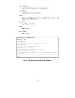
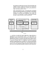
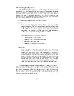
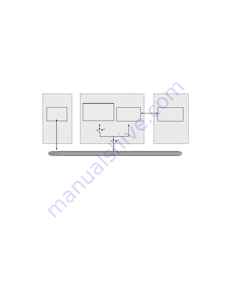
The overview of operation flow for the Fig. 3-53 is quite simple. When
Supplicant PAE issues a request to Authenticator PAE, Authenticator and
Supplicant exchanges authentication message. Then, Authenticator
passes the request to RADIUS server to verify. Finally, RADIUS server
replies if the request is granted or denied.
While in the authentication process, the message packets, encapsulated
by Extensible Authentication Protocol over LAN (EAPOL), are exchanged
between an authenticator PAE and a supplicant PAE. The Authenticator
exchanges the message to authentication server using EAP
encapsulation. Before successfully authenticating, the supplicant can
only touch the authenticator to perform authentication message
exchange or access the network from the uncontrolled port.
Fig. 3-53
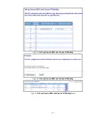
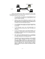
In the Fig. 3-54, this is the typical configuration, a single supplicant, an
authenticator and an authentication server. B and C is in the internal network, D is
Authentication server running RADIUS, switch at the central location acts
Authenticator connecting to PC A and A is a PC outside the controlled port, running
Supplicant PAE. In this case, PC A wants to access the services on device B and C,
first, it must exchange the authentication message with the authenticator on the port
it connected via EAPOL packet. The authenticator transfers the supplicant’s
credentials to Authentication server for verification. If success, the authentication
server will notice the authenticator the grant. PC A, then, is allowed to access B and
C via the switch. If there are two switches directly connected together instead of
single one, for the link connecting two switches, it may have to act two port roles at
the end of the link: authenticator and supplicant, because the traffic is bi-directional.
LAN
Authenticator
PAE
Services Offered
by Authenticator
(e.g Bridge Relay)
Authenticator’s System
Authentication
Server’s System
Authentication
Server
Supplicant
PAE
Supplicant’s
System
Uncontrolled port
Controlled port
MAC Enable
Port Authorize
Summary of Contents for GS-2224L
Page 1: ......
Page 2: ......
Page 34: ...24 Fig 2 15 Office Network Connection Fig 2 14 Peer to peer Network Connection ...
Page 78: ...68 Fig 3 28 ...
Page 83: ...73 Fig 3 31 ...
Page 91: ...81 Fig 3 39 Fig 3 40 Fig 3 41 ...
Page 113: ...103 Fig 3 67 Ingress Port Fig 3 68 ...
Page 115: ...105 Fig 3 71 Fig 3 72 Fig 3 73 ARP Fig 3 74 ARP ...
Page 116: ...106 Fig 3 75 ARP Fig 3 76 ARP Fig 3 77 ARP Fig 3 78 ARP ...
Page 117: ...107 Fig 3 79 ARP Fig 3 80 ARP Fig 3 81 ARP Fig 3 82 ARP ...
Page 118: ...108 Fig 3 83 ARP Fig 3 84 ARP Fig 3 85 ARP Fig 3 86 ARP Fig 3 87 ARP ...
Page 119: ...109 Fig 3 88 IPv4 Fig 3 89 IPv4 Fig 3 90 IPv4 ...
Page 120: ...110 Fig 3 91 IPv4 Fig 3 92 IPv4 Fig 3 93 IPv4 Fig 3 94 IPv4 Fig 3 95 IPv4 ...
Page 121: ...111 Fig 3 96 IPv4 Fig 3 97 IPv4 Fig 3 98 IPv4 Fig 3 99 IPv4 Fig 3 100 IPv4 ...
Page 122: ...112 Fig 3 101 IPv4 Fig 3 102 IPv4 Fig 3 103 IPv4 Fig 3 104 IPv4 ...
Page 123: ...113 Fig 3 105 IPv4 Fig 3 106 IPv4 Fig 3 107 IPv4 ...
Page 124: ...114 Fig 3 108 IPv4 Fig 3 109 IPv4 Fig 3 110 IPv4 Fig 3 111 IPv4 ...
Page 125: ...115 Fig 3 112 IPv4 Fig 3 113 IPv4 Fig 3 114 IPv4 ...
Page 126: ...116 Fig 3 115 IPv4 Fig 3 116 IPv4 Fig 3 117 IPv4 ...
Page 127: ...117 Fig 3 118 Action Fig 3 119 Rate Limiter ...
Page 128: ...118 Fig 3 120 Port Copy Fig 3 121 DMAC Filter ...
Page 129: ...119 Fig 3 122 VLAN ID Filter Fig 3 123 VLAN ID Filter Fig 3 124 Tag Priority ...
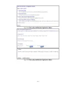
Page 141: ...131 Fig 3 126 Set up Policy Rules Fig 3 127 Set up Policy Rules Fig 3 128 Set up Policy Rules ...
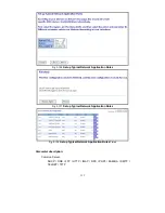
Page 143: ...133 Fig 3 132 Set up Port Policies Fig 3 133 Set up Port Policies Finish ...
Page 159: ...149 Fig 3 145 ...
Page 204: ...194 Fig 4 1 Fig 4 2 ...


