


20
10
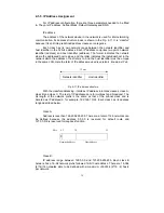
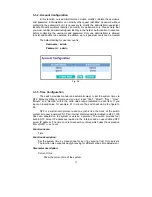
Class C:
IP address range between 192.0.0.0 and 223.255.255.255. Each class C
network has a 24-bit network prefix followed 8-bit host address. There are
2,097,152 (2^21)/24 networks able to be defined with a maximum of 254 (2^8 –2)
hosts per network.
110
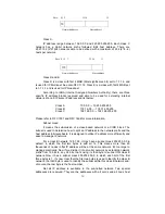
Class D and E:
Class D is a class with first 4 MSB (Most significance bit) set to 1-1-1-0 and
is used for IP Multicast. See also RFC 1112. Class E is a class with first 4 MSB set
to 1-1-1-1 and is used for IP broadcast.
According to IANA (Internet Assigned Numbers Authority), there are three
specific IP address blocks reserved and able to be used for extending internal
network. We call it Private IP address and list below:
Class A
10.0.0.0 --- 10.255.255.255
Class B
172.16.0.0 --- 172.31.255.255
Class C
192.168.0.0 --- 192.168.255.255
Please refer to RFC 1597 and RFC 1466 for more information.
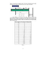
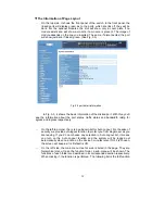
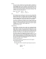
Subnet mask:
It means the sub-division of a class-based network or a CIDR block. The
subnet is used to determine how to split an IP address to the network prefix and the
host address in bitwise basis. It is designed to utilize IP address more efficiently and
ease to manage IP network.
For a class B network, 128.1.2.3, it may have a subnet mask 255.255.0.0 in
default, in which the first two bytes is with all 1s. This means more than 60
thousands of nodes in flat IP address will be at the same network. It’s too large to
manage practically. Now if we divide it into smaller network by extending network
prefix from 16 bits to, say 24 bits, that’s using its third byte to subnet this class B
network. Now it has a subnet mask 255.255.255.0, in which each bit of the first
three bytes is 1. It’s now clear that the first two bytes is used to identify the class B
network, the third byte is used to identify the subnet within this class B network and,
of course, the last byte is the host number.
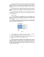
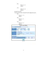
Not all IP address is available in the sub-netted network. Two special
addresses are reserved. They are the addresses with all zero’s and all one’s host
Bit # 01 2 15 16 31
Network address Host address
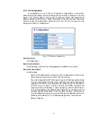
Bit # 0 1 2 3 23 24 31
Network address Host address
Summary of Contents for GS-2224L
Page 1: ......
Page 2: ......
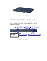
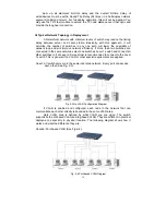
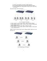
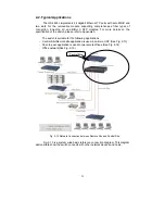
Page 34: ...24 Fig 2 15 Office Network Connection Fig 2 14 Peer to peer Network Connection ...
Page 78: ...68 Fig 3 28 ...
Page 83: ...73 Fig 3 31 ...
Page 91: ...81 Fig 3 39 Fig 3 40 Fig 3 41 ...
Page 113: ...103 Fig 3 67 Ingress Port Fig 3 68 ...
Page 115: ...105 Fig 3 71 Fig 3 72 Fig 3 73 ARP Fig 3 74 ARP ...
Page 116: ...106 Fig 3 75 ARP Fig 3 76 ARP Fig 3 77 ARP Fig 3 78 ARP ...
Page 117: ...107 Fig 3 79 ARP Fig 3 80 ARP Fig 3 81 ARP Fig 3 82 ARP ...
Page 118: ...108 Fig 3 83 ARP Fig 3 84 ARP Fig 3 85 ARP Fig 3 86 ARP Fig 3 87 ARP ...
Page 119: ...109 Fig 3 88 IPv4 Fig 3 89 IPv4 Fig 3 90 IPv4 ...
Page 120: ...110 Fig 3 91 IPv4 Fig 3 92 IPv4 Fig 3 93 IPv4 Fig 3 94 IPv4 Fig 3 95 IPv4 ...
Page 121: ...111 Fig 3 96 IPv4 Fig 3 97 IPv4 Fig 3 98 IPv4 Fig 3 99 IPv4 Fig 3 100 IPv4 ...
Page 122: ...112 Fig 3 101 IPv4 Fig 3 102 IPv4 Fig 3 103 IPv4 Fig 3 104 IPv4 ...
Page 123: ...113 Fig 3 105 IPv4 Fig 3 106 IPv4 Fig 3 107 IPv4 ...
Page 124: ...114 Fig 3 108 IPv4 Fig 3 109 IPv4 Fig 3 110 IPv4 Fig 3 111 IPv4 ...
Page 125: ...115 Fig 3 112 IPv4 Fig 3 113 IPv4 Fig 3 114 IPv4 ...
Page 126: ...116 Fig 3 115 IPv4 Fig 3 116 IPv4 Fig 3 117 IPv4 ...
Page 127: ...117 Fig 3 118 Action Fig 3 119 Rate Limiter ...
Page 128: ...118 Fig 3 120 Port Copy Fig 3 121 DMAC Filter ...
Page 129: ...119 Fig 3 122 VLAN ID Filter Fig 3 123 VLAN ID Filter Fig 3 124 Tag Priority ...
Page 141: ...131 Fig 3 126 Set up Policy Rules Fig 3 127 Set up Policy Rules Fig 3 128 Set up Policy Rules ...
Page 143: ...133 Fig 3 132 Set up Port Policies Fig 3 133 Set up Port Policies Finish ...
Page 159: ...149 Fig 3 145 ...
Page 204: ...194 Fig 4 1 Fig 4 2 ...


