


17
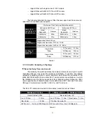
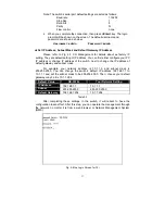
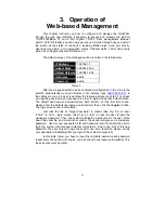
Note: The switch’s serial port default settings are listed as follows:
Baud rate
115200
Stop
bits
1
Data bits
8
Parity
N
Flow
control
none
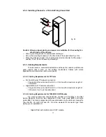
4.
When you complete the connection, then press
<Enter>
key.
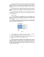
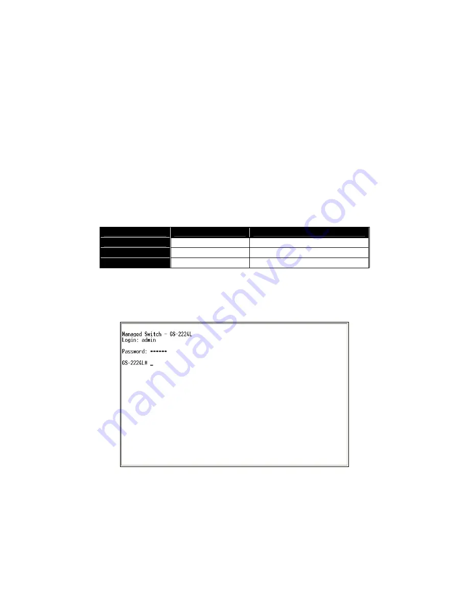
The login
prompt will be shown on the screen. The default username and
password are shown as below:
Username = admin Password = admin
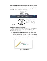
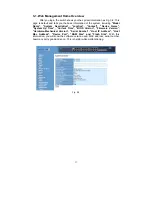
•
Set IP Address, Subnet Mask and Default Gateway IP Address
Please refer to Fig. 2-7 CLI Management for details about ex-factory IP
setting. They are default setting of IP address. You can first either configure your PC
IP address or change IP address of the switch, next to change the IP address of
default gateway and subnet mask.
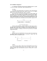
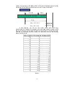
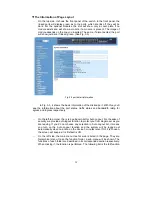
For example, your network address is 10.1.1.0, and subnet mask is
255.255.255.0. You can change the switch’s default IP address 192.168.1.1 to
10.1.1.1 and set the subnet mask to be 255.255.255.0. Then, choose your default
gateway, may be it is 10.1.1.254.
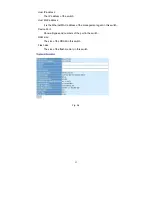
Default Value
GS-2224L
Your Network Setting
IP Address
192.168.1.1 10.1.1.1
Subnet
255.255.255.0 255.255.255.0
Default Gateway
192.168.1.254 10.1.1.254
Table 2-3
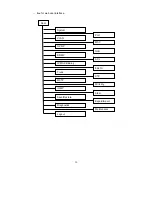
After completing these settings in the switch, it will reboot to have the
configuration taken effect. After this step, you can operate the management through
the network, no matter it is from a web browser or Network Management System
(NMS).
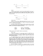
Fig. 2-8 the Login Screen for CLI
Summary of Contents for GS-2224L
Page 1: ......
Page 2: ......
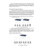
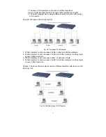
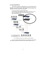
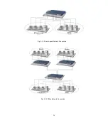
Page 34: ...24 Fig 2 15 Office Network Connection Fig 2 14 Peer to peer Network Connection ...
Page 78: ...68 Fig 3 28 ...
Page 83: ...73 Fig 3 31 ...
Page 91: ...81 Fig 3 39 Fig 3 40 Fig 3 41 ...
Page 113: ...103 Fig 3 67 Ingress Port Fig 3 68 ...
Page 115: ...105 Fig 3 71 Fig 3 72 Fig 3 73 ARP Fig 3 74 ARP ...
Page 116: ...106 Fig 3 75 ARP Fig 3 76 ARP Fig 3 77 ARP Fig 3 78 ARP ...
Page 117: ...107 Fig 3 79 ARP Fig 3 80 ARP Fig 3 81 ARP Fig 3 82 ARP ...
Page 118: ...108 Fig 3 83 ARP Fig 3 84 ARP Fig 3 85 ARP Fig 3 86 ARP Fig 3 87 ARP ...
Page 119: ...109 Fig 3 88 IPv4 Fig 3 89 IPv4 Fig 3 90 IPv4 ...
Page 120: ...110 Fig 3 91 IPv4 Fig 3 92 IPv4 Fig 3 93 IPv4 Fig 3 94 IPv4 Fig 3 95 IPv4 ...
Page 121: ...111 Fig 3 96 IPv4 Fig 3 97 IPv4 Fig 3 98 IPv4 Fig 3 99 IPv4 Fig 3 100 IPv4 ...
Page 122: ...112 Fig 3 101 IPv4 Fig 3 102 IPv4 Fig 3 103 IPv4 Fig 3 104 IPv4 ...
Page 123: ...113 Fig 3 105 IPv4 Fig 3 106 IPv4 Fig 3 107 IPv4 ...
Page 124: ...114 Fig 3 108 IPv4 Fig 3 109 IPv4 Fig 3 110 IPv4 Fig 3 111 IPv4 ...
Page 125: ...115 Fig 3 112 IPv4 Fig 3 113 IPv4 Fig 3 114 IPv4 ...
Page 126: ...116 Fig 3 115 IPv4 Fig 3 116 IPv4 Fig 3 117 IPv4 ...
Page 127: ...117 Fig 3 118 Action Fig 3 119 Rate Limiter ...
Page 128: ...118 Fig 3 120 Port Copy Fig 3 121 DMAC Filter ...
Page 129: ...119 Fig 3 122 VLAN ID Filter Fig 3 123 VLAN ID Filter Fig 3 124 Tag Priority ...
Page 141: ...131 Fig 3 126 Set up Policy Rules Fig 3 127 Set up Policy Rules Fig 3 128 Set up Policy Rules ...
Page 143: ...133 Fig 3 132 Set up Port Policies Fig 3 133 Set up Port Policies Finish ...
Page 159: ...149 Fig 3 145 ...
Page 204: ...194 Fig 4 1 Fig 4 2 ...


