


6
•
Supports 802.1Q VLAN
•
Supports user management and limits three users to login
•
Maximal packet length can be up to 9600 bytes for jumbo frame application
•
Supports DHCP Broadcasting Suppression to avoid network suspended or
crashed
•
Supports to send the trap event while monitored events happened
•
Supports default configuration which can be restored to overwrite the current
configuration which is working on via web browser and CLI
•
Supports on-line plug/unplug SFP modules
•
Supports Quality of Service (QoS) for real time applications based on the
information taken from Layer 2 to Layer 4, such as VoIP
•
Built-in web-based management and CLI management, providing a more
convenient UI for the user
•
Supports port mirror function with ingress/egress traffic
•
Supports rapid spanning tree (802.1w RSTP)
•
Supports multiple spanning tree (802.1s MSTP)
•
Supports 802.1X port security on a VLAN
•
Supports IP-MAC-Port Binding for LAN security
•
Supports user management and only first login administrator can configure the
device. The rest of users can only view the switch
•
SNMP access can be disabled and prevent from illegal SNMP access
•
Supports Ingress, Non-unicast and Egress
Bandwidth rating management with
a resolution of 1Mbps
•
The trap event and alarm message can be transferred via e-mail
•
Supports diagnostics to let administrator knowing the hardware status
•
Supports loop detection to protect the switch crash when the networking has
looping issue
•
HTTP and TFTP for firmware upgrade, system log upload and configuration file
import/export
•
Supports remote boot the device through user interface and SNMP
•
Supports NTP network time synchronization and daylight saving
•
Supports 120 event log records in the main memory and display on the local
console
Summary of Contents for GS-2224L
Page 1: ......
Page 2: ......
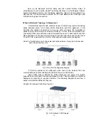
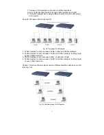
Page 34: ...24 Fig 2 15 Office Network Connection Fig 2 14 Peer to peer Network Connection ...
Page 78: ...68 Fig 3 28 ...
Page 83: ...73 Fig 3 31 ...
Page 91: ...81 Fig 3 39 Fig 3 40 Fig 3 41 ...
Page 113: ...103 Fig 3 67 Ingress Port Fig 3 68 ...
Page 115: ...105 Fig 3 71 Fig 3 72 Fig 3 73 ARP Fig 3 74 ARP ...
Page 116: ...106 Fig 3 75 ARP Fig 3 76 ARP Fig 3 77 ARP Fig 3 78 ARP ...
Page 117: ...107 Fig 3 79 ARP Fig 3 80 ARP Fig 3 81 ARP Fig 3 82 ARP ...
Page 118: ...108 Fig 3 83 ARP Fig 3 84 ARP Fig 3 85 ARP Fig 3 86 ARP Fig 3 87 ARP ...
Page 119: ...109 Fig 3 88 IPv4 Fig 3 89 IPv4 Fig 3 90 IPv4 ...
Page 120: ...110 Fig 3 91 IPv4 Fig 3 92 IPv4 Fig 3 93 IPv4 Fig 3 94 IPv4 Fig 3 95 IPv4 ...
Page 121: ...111 Fig 3 96 IPv4 Fig 3 97 IPv4 Fig 3 98 IPv4 Fig 3 99 IPv4 Fig 3 100 IPv4 ...
Page 122: ...112 Fig 3 101 IPv4 Fig 3 102 IPv4 Fig 3 103 IPv4 Fig 3 104 IPv4 ...
Page 123: ...113 Fig 3 105 IPv4 Fig 3 106 IPv4 Fig 3 107 IPv4 ...
Page 124: ...114 Fig 3 108 IPv4 Fig 3 109 IPv4 Fig 3 110 IPv4 Fig 3 111 IPv4 ...
Page 125: ...115 Fig 3 112 IPv4 Fig 3 113 IPv4 Fig 3 114 IPv4 ...
Page 126: ...116 Fig 3 115 IPv4 Fig 3 116 IPv4 Fig 3 117 IPv4 ...
Page 127: ...117 Fig 3 118 Action Fig 3 119 Rate Limiter ...
Page 128: ...118 Fig 3 120 Port Copy Fig 3 121 DMAC Filter ...
Page 129: ...119 Fig 3 122 VLAN ID Filter Fig 3 123 VLAN ID Filter Fig 3 124 Tag Priority ...
Page 141: ...131 Fig 3 126 Set up Policy Rules Fig 3 127 Set up Policy Rules Fig 3 128 Set up Policy Rules ...
Page 143: ...133 Fig 3 132 Set up Port Policies Fig 3 133 Set up Port Policies Finish ...
Page 159: ...149 Fig 3 145 ...
Page 204: ...194 Fig 4 1 Fig 4 2 ...


