


22
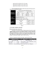
According to the scheme above, a subnet mask 255.255.255.0 will partition a
network with the class C. It means there will have a maximum of 254 effective
nodes existed in this sub-netted network and is considered a physical network in an
autonomous network. So it owns a network IP address which may looks like
168.1.2.0.
With the subnet mask, a bigger network can be cut into small pieces of
network. If we want to have more than two independent networks in a worknet, a
partition to the network must be performed. In this case, subnet mask must be
applied.
For different network applications, the subnet mask may look like
255.255.255.240. This means it is a small network accommodating a maximum of
15 nodes in the network.
Default gateway:
For the routed packet, if the destination is not in the routing table, all the
traffic is put into the device with the designated IP address, known as default router.
Basically, it is a routing policy. The gateway setting is used for Trap Events Host
only in the switch.
For assigning an IP address to the switch, you just have to check what the IP
address of the network will be connected with the switch. Use the same network
address and append your host address to it.
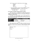
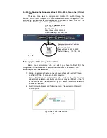
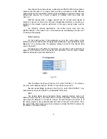
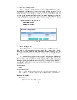
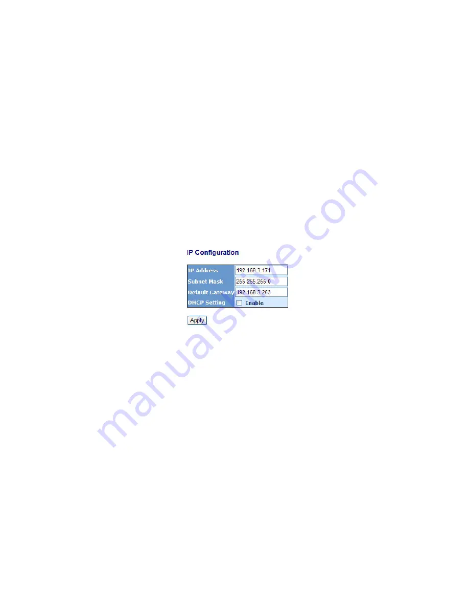
Fig. 2-12
First, IP Address: as shown in the Fig. 2-12, enter “192.168.1.1”, for instance.
For sure, an IP address such as 192.168.1.x must be set on your PC.
Second, Subnet Mask: as shown in the Fig. 2-12, enter “255.255.255.0”. Any
subnet mask such as 255.255.255.x is allowable in this case.
DNS:
The Domain Name Server translates human readable machine name to IP
address. Every machine on the Internet has a unique IP address. A server generally
has a static IP address. To connect to a server, the client needs to know the IP of
the server. However, user generally uses the name to connect to the server. Thus,
the switch DNS client program (such as a browser) will ask the DNS to resolve the
IP address of the named server.
Summary of Contents for GS-2224L
Page 1: ......
Page 2: ......
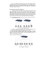
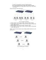
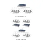
Page 34: ...24 Fig 2 15 Office Network Connection Fig 2 14 Peer to peer Network Connection ...
Page 78: ...68 Fig 3 28 ...
Page 83: ...73 Fig 3 31 ...
Page 91: ...81 Fig 3 39 Fig 3 40 Fig 3 41 ...
Page 113: ...103 Fig 3 67 Ingress Port Fig 3 68 ...
Page 115: ...105 Fig 3 71 Fig 3 72 Fig 3 73 ARP Fig 3 74 ARP ...
Page 116: ...106 Fig 3 75 ARP Fig 3 76 ARP Fig 3 77 ARP Fig 3 78 ARP ...
Page 117: ...107 Fig 3 79 ARP Fig 3 80 ARP Fig 3 81 ARP Fig 3 82 ARP ...
Page 118: ...108 Fig 3 83 ARP Fig 3 84 ARP Fig 3 85 ARP Fig 3 86 ARP Fig 3 87 ARP ...
Page 119: ...109 Fig 3 88 IPv4 Fig 3 89 IPv4 Fig 3 90 IPv4 ...
Page 120: ...110 Fig 3 91 IPv4 Fig 3 92 IPv4 Fig 3 93 IPv4 Fig 3 94 IPv4 Fig 3 95 IPv4 ...
Page 121: ...111 Fig 3 96 IPv4 Fig 3 97 IPv4 Fig 3 98 IPv4 Fig 3 99 IPv4 Fig 3 100 IPv4 ...
Page 122: ...112 Fig 3 101 IPv4 Fig 3 102 IPv4 Fig 3 103 IPv4 Fig 3 104 IPv4 ...
Page 123: ...113 Fig 3 105 IPv4 Fig 3 106 IPv4 Fig 3 107 IPv4 ...
Page 124: ...114 Fig 3 108 IPv4 Fig 3 109 IPv4 Fig 3 110 IPv4 Fig 3 111 IPv4 ...
Page 125: ...115 Fig 3 112 IPv4 Fig 3 113 IPv4 Fig 3 114 IPv4 ...
Page 126: ...116 Fig 3 115 IPv4 Fig 3 116 IPv4 Fig 3 117 IPv4 ...
Page 127: ...117 Fig 3 118 Action Fig 3 119 Rate Limiter ...
Page 128: ...118 Fig 3 120 Port Copy Fig 3 121 DMAC Filter ...
Page 129: ...119 Fig 3 122 VLAN ID Filter Fig 3 123 VLAN ID Filter Fig 3 124 Tag Priority ...
Page 141: ...131 Fig 3 126 Set up Policy Rules Fig 3 127 Set up Policy Rules Fig 3 128 Set up Policy Rules ...
Page 143: ...133 Fig 3 132 Set up Port Policies Fig 3 133 Set up Port Policies Finish ...
Page 159: ...149 Fig 3 145 ...
Page 204: ...194 Fig 4 1 Fig 4 2 ...


