


143
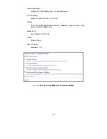
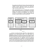
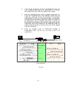
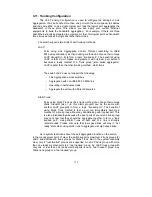
The Fig. 3-55 shows the procedure of 802.1X authentication. There are steps
for the login based on 802.1X port access control management. The protocol used
in the right side is EAPOL and the left side is EAP.
1.
At the initial stage, the supplicant A is unauthenticated and a port
on switch acting as an authenticator is in unauthorized state. So the
access is blocked in this stage.
2.
Initiating a session. Either authenticator or supplicant can initiate
the message exchange. If supplicant initiates the process, it sends
EAPOL-start packet to the authenticator PAE and authenticator will
immediately respond EAP-Request/Identity packet.
3. The
authenticator
always periodically sends EAP-Request/Identity
to the supplicant for requesting the identity it wants to be
authenticated.
4. If the authenticator doesn’t send EAP-Request/Identity, the
supplicant will initiate EAPOL-Start the process by sending to the
authenticator.
5.
And next, the Supplicant replies an EAP-Response/Identity to the
authenticator. The authenticator will embed the user ID into Radius-
Access-Request command and send it to the authentication server
for confirming its identity.
6.
After receiving the Radius-Access-Request, the authentication
server sends Radius-Access-Challenge to the supplicant for asking
for inputting user password via the authenticator PAE.
7.
The supplicant will convert user password into the credential
information, perhaps, in MD5 format and replies an EAP-Response
with this credential information as well as the specified
authentication algorithm (MD5 or OTP) to Authentication server via
the authenticator PAE. As per the value of the type field in message
PDU, the authentication server knows which algorithm should be
applied to authenticate the credential information, EAP-MD5
(Message Digest 5) or EAP-OTP (One Time Password) or other
else algorithm.
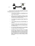
Supplicant A
B
C
Authentication server
Authenticator
Fig. 3-54
Summary of Contents for GS-2224L
Page 1: ......
Page 2: ......
Page 34: ...24 Fig 2 15 Office Network Connection Fig 2 14 Peer to peer Network Connection ...
Page 78: ...68 Fig 3 28 ...
Page 83: ...73 Fig 3 31 ...
Page 91: ...81 Fig 3 39 Fig 3 40 Fig 3 41 ...
Page 113: ...103 Fig 3 67 Ingress Port Fig 3 68 ...
Page 115: ...105 Fig 3 71 Fig 3 72 Fig 3 73 ARP Fig 3 74 ARP ...
Page 116: ...106 Fig 3 75 ARP Fig 3 76 ARP Fig 3 77 ARP Fig 3 78 ARP ...
Page 117: ...107 Fig 3 79 ARP Fig 3 80 ARP Fig 3 81 ARP Fig 3 82 ARP ...
Page 118: ...108 Fig 3 83 ARP Fig 3 84 ARP Fig 3 85 ARP Fig 3 86 ARP Fig 3 87 ARP ...
Page 119: ...109 Fig 3 88 IPv4 Fig 3 89 IPv4 Fig 3 90 IPv4 ...
Page 120: ...110 Fig 3 91 IPv4 Fig 3 92 IPv4 Fig 3 93 IPv4 Fig 3 94 IPv4 Fig 3 95 IPv4 ...
Page 121: ...111 Fig 3 96 IPv4 Fig 3 97 IPv4 Fig 3 98 IPv4 Fig 3 99 IPv4 Fig 3 100 IPv4 ...
Page 122: ...112 Fig 3 101 IPv4 Fig 3 102 IPv4 Fig 3 103 IPv4 Fig 3 104 IPv4 ...
Page 123: ...113 Fig 3 105 IPv4 Fig 3 106 IPv4 Fig 3 107 IPv4 ...
Page 124: ...114 Fig 3 108 IPv4 Fig 3 109 IPv4 Fig 3 110 IPv4 Fig 3 111 IPv4 ...
Page 125: ...115 Fig 3 112 IPv4 Fig 3 113 IPv4 Fig 3 114 IPv4 ...
Page 126: ...116 Fig 3 115 IPv4 Fig 3 116 IPv4 Fig 3 117 IPv4 ...
Page 127: ...117 Fig 3 118 Action Fig 3 119 Rate Limiter ...
Page 128: ...118 Fig 3 120 Port Copy Fig 3 121 DMAC Filter ...
Page 129: ...119 Fig 3 122 VLAN ID Filter Fig 3 123 VLAN ID Filter Fig 3 124 Tag Priority ...
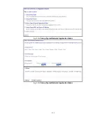
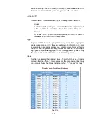
Page 141: ...131 Fig 3 126 Set up Policy Rules Fig 3 127 Set up Policy Rules Fig 3 128 Set up Policy Rules ...
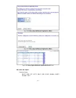
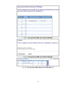
Page 143: ...133 Fig 3 132 Set up Port Policies Fig 3 133 Set up Port Policies Finish ...
Page 159: ...149 Fig 3 145 ...
Page 204: ...194 Fig 4 1 Fig 4 2 ...


