


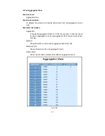
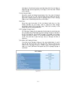

153
Per Trunking Group supports a maximum of 12 ready member-ports. Please
note that some decisions will automatically be made by the system while you are
configuring your trunking ports. Some configuration examples are listed below:
a) 12 ports have already used Static Trunk Group ID 1, the 13th port
willing to use the same Static Trunk Group ID will be automatically set
to use the “None” trunking method and its Group ID will turn to 0. This
means the port won’t aggregate with other ports.
b) 14 ports all use LACP Trunk Group ID 1 at most 12 ports can
aggregate together and transit into the ready state.
c) A port using the “None“ trunking method or Group ID 0 will be
automatically set to use the “None” trunking method with Group ID 0.
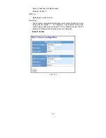
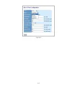
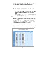
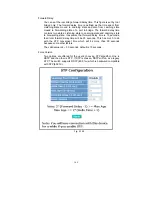
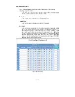
3-11-1.Port
Function name:
Trunk Port Setting/Status
Function description:
Port setting/status is used to configure the trunk property of each and every
port in the switch system.
Parameter description:
Port:
Port Number: 1-24
Method:
This determines the method a port uses to aggregate with other ports.
None:
A port does not want to aggregate with any other port should
choose this default setting.
LACP:
A port use LACP as its trunk method to get aggregated with other
ports also using LACP.
Static:
A port use Static Trunk as its trunk method to get aggregated with
other ports also using Static Trunk.
Group:
Ports choosing the same trunking method other than “None” must be
Summary of Contents for GS-2224L
Page 1: ......
Page 2: ......
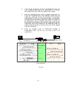
Page 34: ...24 Fig 2 15 Office Network Connection Fig 2 14 Peer to peer Network Connection ...
Page 78: ...68 Fig 3 28 ...
Page 83: ...73 Fig 3 31 ...
Page 91: ...81 Fig 3 39 Fig 3 40 Fig 3 41 ...
Page 113: ...103 Fig 3 67 Ingress Port Fig 3 68 ...
Page 115: ...105 Fig 3 71 Fig 3 72 Fig 3 73 ARP Fig 3 74 ARP ...
Page 116: ...106 Fig 3 75 ARP Fig 3 76 ARP Fig 3 77 ARP Fig 3 78 ARP ...
Page 117: ...107 Fig 3 79 ARP Fig 3 80 ARP Fig 3 81 ARP Fig 3 82 ARP ...
Page 118: ...108 Fig 3 83 ARP Fig 3 84 ARP Fig 3 85 ARP Fig 3 86 ARP Fig 3 87 ARP ...
Page 119: ...109 Fig 3 88 IPv4 Fig 3 89 IPv4 Fig 3 90 IPv4 ...
Page 120: ...110 Fig 3 91 IPv4 Fig 3 92 IPv4 Fig 3 93 IPv4 Fig 3 94 IPv4 Fig 3 95 IPv4 ...
Page 121: ...111 Fig 3 96 IPv4 Fig 3 97 IPv4 Fig 3 98 IPv4 Fig 3 99 IPv4 Fig 3 100 IPv4 ...
Page 122: ...112 Fig 3 101 IPv4 Fig 3 102 IPv4 Fig 3 103 IPv4 Fig 3 104 IPv4 ...
Page 123: ...113 Fig 3 105 IPv4 Fig 3 106 IPv4 Fig 3 107 IPv4 ...
Page 124: ...114 Fig 3 108 IPv4 Fig 3 109 IPv4 Fig 3 110 IPv4 Fig 3 111 IPv4 ...
Page 125: ...115 Fig 3 112 IPv4 Fig 3 113 IPv4 Fig 3 114 IPv4 ...
Page 126: ...116 Fig 3 115 IPv4 Fig 3 116 IPv4 Fig 3 117 IPv4 ...
Page 127: ...117 Fig 3 118 Action Fig 3 119 Rate Limiter ...
Page 128: ...118 Fig 3 120 Port Copy Fig 3 121 DMAC Filter ...
Page 129: ...119 Fig 3 122 VLAN ID Filter Fig 3 123 VLAN ID Filter Fig 3 124 Tag Priority ...
Page 141: ...131 Fig 3 126 Set up Policy Rules Fig 3 127 Set up Policy Rules Fig 3 128 Set up Policy Rules ...
Page 143: ...133 Fig 3 132 Set up Port Policies Fig 3 133 Set up Port Policies Finish ...
Page 159: ...149 Fig 3 145 ...
Page 204: ...194 Fig 4 1 Fig 4 2 ...


