42
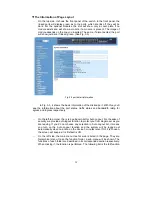
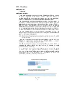
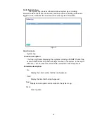
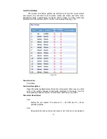
3-1-7. Virtual Stack
Function name:
Virtual Stack
Function description:
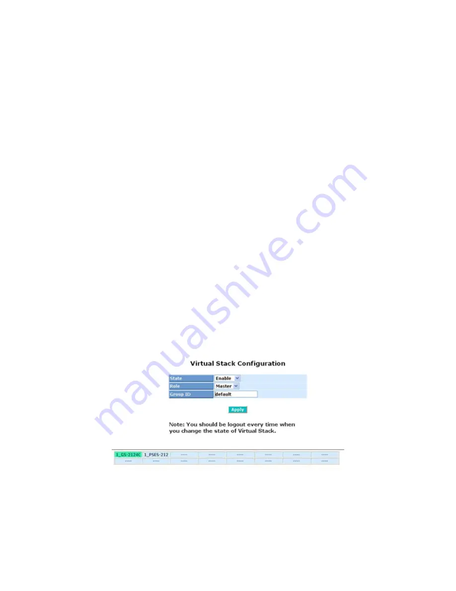
Virtual Stack Management(VSM) is the group management function. Through
the proper configuration of this function, switches in the same LAN will be
grouped automatically. And among these switch, one switch will be a master
machine, and the others in this group will become the slave devices.
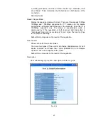
VSM offers a simple centralized management function. It is not necessary to
remember the address of all devices, manager is capable of managing the
network with knowing the address of the Master machine. Instead of SNMP or
Telnet UI, VSM is only available in Web UI. While one switch become the
Master, two rows of buttons for group device will appear on the top of its Web
UI. By pressing these buttons, user will be allowed to connect the Web UI of
the devices of the group in the same window without the login of these device.
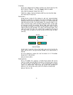
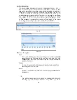
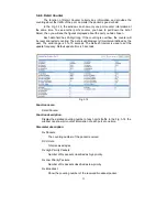
The most top-left button is only for Master device(See Fig.3-9). The
background color of the button you press will be changed to represent that the
device is under your management.
Note: It will remove the grouping temporarily in case that you login the switch
via the console.
The device of the group will be shown as station address ( the last number of
IP Address) + device name
on the button (e.g. 196_GS-2224L), otherwise it
will show ” ---- “ if no corresponding device exists.
Once the devices join the group successfully, then they are merely able to be
managed via Master device, and user will fail to manage them via
telnet/console/web individually.
Up to 16 devices can be grouped for VSM, however, only one Master is
allowed to exist in each group. For Master redundancy, user may configure
more than two devices as Master device, however, the Master device with the
smaller MAC value will be the Master one. All of these 16 devices can
become Master device and back up with each other .
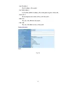
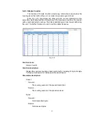
Fig. 3-10-1
Summary of Contents for GS-2224L
Page 1: ......
Page 2: ......
Page 34: ...24 Fig 2 15 Office Network Connection Fig 2 14 Peer to peer Network Connection ...
Page 78: ...68 Fig 3 28 ...
Page 83: ...73 Fig 3 31 ...
Page 91: ...81 Fig 3 39 Fig 3 40 Fig 3 41 ...
Page 113: ...103 Fig 3 67 Ingress Port Fig 3 68 ...
Page 115: ...105 Fig 3 71 Fig 3 72 Fig 3 73 ARP Fig 3 74 ARP ...
Page 116: ...106 Fig 3 75 ARP Fig 3 76 ARP Fig 3 77 ARP Fig 3 78 ARP ...
Page 117: ...107 Fig 3 79 ARP Fig 3 80 ARP Fig 3 81 ARP Fig 3 82 ARP ...
Page 118: ...108 Fig 3 83 ARP Fig 3 84 ARP Fig 3 85 ARP Fig 3 86 ARP Fig 3 87 ARP ...
Page 119: ...109 Fig 3 88 IPv4 Fig 3 89 IPv4 Fig 3 90 IPv4 ...
Page 120: ...110 Fig 3 91 IPv4 Fig 3 92 IPv4 Fig 3 93 IPv4 Fig 3 94 IPv4 Fig 3 95 IPv4 ...
Page 121: ...111 Fig 3 96 IPv4 Fig 3 97 IPv4 Fig 3 98 IPv4 Fig 3 99 IPv4 Fig 3 100 IPv4 ...
Page 122: ...112 Fig 3 101 IPv4 Fig 3 102 IPv4 Fig 3 103 IPv4 Fig 3 104 IPv4 ...
Page 123: ...113 Fig 3 105 IPv4 Fig 3 106 IPv4 Fig 3 107 IPv4 ...
Page 124: ...114 Fig 3 108 IPv4 Fig 3 109 IPv4 Fig 3 110 IPv4 Fig 3 111 IPv4 ...
Page 125: ...115 Fig 3 112 IPv4 Fig 3 113 IPv4 Fig 3 114 IPv4 ...
Page 126: ...116 Fig 3 115 IPv4 Fig 3 116 IPv4 Fig 3 117 IPv4 ...
Page 127: ...117 Fig 3 118 Action Fig 3 119 Rate Limiter ...
Page 128: ...118 Fig 3 120 Port Copy Fig 3 121 DMAC Filter ...
Page 129: ...119 Fig 3 122 VLAN ID Filter Fig 3 123 VLAN ID Filter Fig 3 124 Tag Priority ...
Page 141: ...131 Fig 3 126 Set up Policy Rules Fig 3 127 Set up Policy Rules Fig 3 128 Set up Policy Rules ...
Page 143: ...133 Fig 3 132 Set up Port Policies Fig 3 133 Set up Port Policies Finish ...
Page 159: ...149 Fig 3 145 ...
Page 204: ...194 Fig 4 1 Fig 4 2 ...


