Subject to change.
Roto E-Tec DoorDrive
IMO_294_EN_v0
May 2013
23
Installation
Installation steps
14.
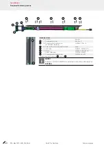
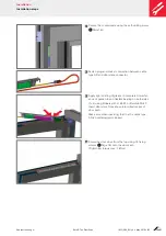
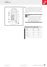
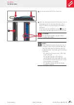
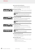
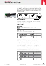
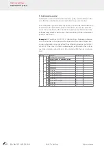
Strip the required wires (refer to Table 1 or sketch on
left) on cable type SD to 9 mm. Connect the stripped
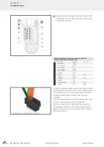
wires to the plug-and-socket connector X1 denoted
by the white dot, as per Table 1. The contacts are
numbered at the side on the connector The wires are
coloured.
NOTE!
When shortening the cable it is advisable to
strip the insulation for an area of at least
5 cm, because the cable in the stripped
insulation area is flexible, this in turn ena-
bles the excess length required in the
profile to be simply cleared away.
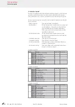
Table 1: Assignment of plug-and-socket connector X1
to the door /to the spindle drive on cable harness 1
Contact Description
Abbreviation
Wire colour
1
Motor +
M+
Red
2
Motor –
M–
Black
3
Hall GND
HGND
Violet
4
5
Hall Vcc
HVCC
Yellow
6
7
Hall Speed 2
HS2
Green
8
9
Hall Speed 1
HS1
Blue
10
11
12
Summary of Contents for E-Tec DoorDrive
Page 51: ......


