background image

22


 May 2013 

 IMO_294_EN_v0 

Roto E-Tec DoorDrive  

Subject to change.

11.

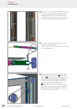
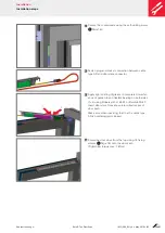
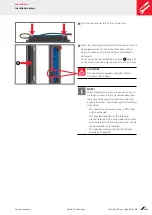
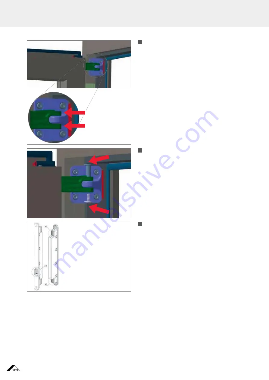
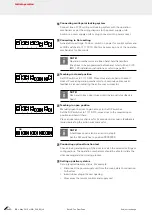
Manually pull the coupling rod approx. 80 mm out of 

the door sash. Then, by moving the door sash, join 
the coupling rod with the angle bracket.
When joining, make sure that the system remains 
free of tension and that the gap widths between the 
coupling rod and the angle bracket are spaced 
equally apart.

12.

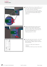
Slide the threaded bushing from above into the 
 coupling rod and through the angle bracket.
Fasten this in place using the fillister head screw. 
When bolting together, press with the finger from 
above onto the threaded bushing.
(Tightening torque max. 2.5 Nm)

13.

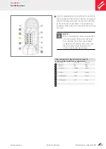
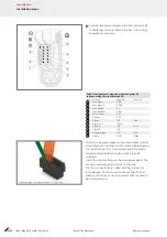
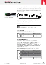
The two plug-and-socket connectors on X1 and X2 
cannot be interchanged, and they have reverse- 
polarity protection.  Therefore, make sure that they 
are wired correctly.

 –  Connect to X1 cable type SD to Roto E-Tec 

DoorDrive.

–   On X2, connect cable type S to the cable junction.

Installation

Installation steps

Summary of Contents for E-Tec DoorDrive

Page 1: ...Window and Door Technology Roto E Tec DoorDrive The concealed swing door drive for doors Installation maintenance and operation instructions for timber and aluminium doors ...

Page 2: ...Imprint Copyright April 2013 Roto Frank AG Wilhelm Frank Platz 1 70771 Leinfelden Echterdingen Germany Telephone 49 711 7598 0 Fax 49 711 7598 253 info roto frank com www roto frank com ...

Page 3: ...al equipment 11 Risks on closing edges and moving components 11 Residual risk 11 System architecture Overview 12 Parts list 13 Scope of delivery for Roto E Tec DoorDrive 13 Permissible performance characteristics 14 Overload protection 14 Installation explanation 15 Installation Preparation 16 System overview 17 Required fastening means 18 Installation steps 19 Wiring Connection diagram for Eneo C...

Page 4: ... closing 36 Fault memory special functions 37 Feedback and errors Signal sequence meaning 38 Feedback 38 Troubleshooting 39 Errors 39 Maintenance Door functions 43 Structural surroundings 44 Lubrication 44 Risk assessment General details 45 Inspect possible hazardous locations on automatic Turn Only sash doors 46 Inspect and check possible hazardous locations and protection measures as per DIN EN ...

Page 5: ...rkings The following signs are used in this manual to highlight handling directives results lists references and other elements Marking Explanation Drill holes 1 Hardware components 1 Action steps First level of hierarchy in a list Unordered list second level of hierarchy p 12 Cross reference in tables Refer to page 12 Cross reference in the text The figures show DIN right hand versions All dimens...

Page 6: ...ing element dealers installation companies The building element dealers target group includes all companies persons who purchase doors from the door manufacturer in order to sell these on and to install them into a building development without modifying them The installation company target group includes all companies persons who purchase doors from the door manufacturer or the building element de...

Page 7: ...ufacturer must ensure that the end user is provided with the docu ments and information intended for them in printed format Responsibility of specialised dealer installation company The specialised dealer must forward the following documents to the builder even when a subcontractor installation company is acting as an intermediary Maintenance and operating instructions with the focus on hardware T...

Page 8: ...hazardous situation which may lead to fatality or serious injuries if it is not avoided Warning This combination of symbol and signal word indicates a potentially hazardous situation that may lead to fatality or serious injuries if it is not avoided Caution This combination of symbol and signal word indicates a potentially hazardous situation which may lead to minor or light injuries if it is not ...

Page 9: ...nadequate invitation to tender failure to comply with the installation instructions Forced opening closing of the door Increased soiling Claims by third parties against the hardware manufacturer on the ground of damages resulting from misuse or failure to follow the instruction obligation on the part of the hardware dealer the door manufacturer and of the specialised dealer or the builder are tran...

Page 10: ...oes beyond or differs from the stipulated use shall be regarded as misuse Warning Danger from misuse improper installation and improper initial operation Misuse and incorrect installation of hardware can result in hazardous situations Never use combinations that have not been approved by the hardware manufacturer Never use accessories that are not original products or that have not been approved b...

Page 11: ...ety of the practical instances into consideration Nevertheless no warranty can be given here for their completeness If you are interested in any additional information please contact your Roto processor Hazards on closing edges and moving components The safety instructions should highlight the possible hazard points on power operated doors and show the affected safeguards or design requirements Da...

Page 12: ...12 May 2013 IMO_294_EN_v0 Roto E Tec DoorDrive Subject to change System architecture Overview Cable junction connection 20 E Tec control unit 30 Cable type SD 40 Cable type S 10 Roto E Tec DoorDrive ...

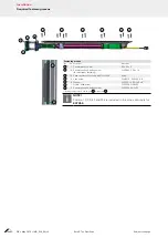
Page 13: ... of delivery Pos Designation Material no 10 Roto E Tec DoorDrive 637922 20 Roto E Tec DoorDrive control unit 637923 30 Cable type SD length 1 5m 637924 40 Cable type S length 1m 637957 Pluggable cable junction 8 pin not depicted 637956 Power supply unit 13V for Roto E Tec DoorDrive not depicted 637955 Counterplate 60x55x5mm incl screws not depicted 637958 ...

Page 14: ... 3 pieces 2 x at top 1 x at bottom depending on type poss 4 Cable junction Pluggable cable junction 8 pin Note At least 3 door hinges 2x at top 1x at bottom must be used The door hinges must fulfil the Class 14 requirements in accordance with EN 1935 Overload protection To avoid any damage to the door and or the swing door drive through slam ming through extreme manual force or wind power the swin...

Page 15: ...Subject to change Roto E Tec DoorDrive IMO_294_EN_v0 May 2013 15 System architecture Installation explanation ...

Page 16: ...ut corner connector as far as required only Make a corresponding corner bracket for reinforcement in the clearance Set the control to match the Roto configuration Refer to page 31 This programming step is best performed in advance e g at the factory Note Installation sequence Install the wiring harness in the door sash before inserting the door panel The drill holes and milling must be conducted i...

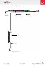
Page 17: ... DoorDrive IMO_294_EN_v0 May 2013 17 Installation System overview The following drawing shows an overall view of the system Cable junction connection E Tec control unit Cable type S Roto E Tec DoorDrive Cable type SD Counterplate ...

Page 18: ...tersunk self drilling screw for aluminium fastening DIN 7982 C 3 9x19 20a 1 14 Spax countersunk screws with Torx TX20 4x40 30 2 4 Allen screw DIN 6912 M5x60 8 8 40 2 4 Washer DIN 125 A 5 3 140HV 50 2 1 Fillister head screw DIN 7504N 3 5x32 60 2 Countersunk self drilling screw DIN 7504P 4 2x32 1 To fasten the door drive in a timber door 20 is replaced by 20a Note Position 10 30 40 and 50 are includ...

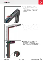
Page 19: ...ecess 2 Route cable type SD into the glazing rebate up to the milled recess for the electronic unit Ensure that the cable here has sufficiently large bending radii Alternatively the cable can also be routed into the profile chamber To do this the cable must however have been inserted before the corner connector is made Drill hole 3 Route the cable type SD through the bore in the glazing rebate int...

Page 20: ...pe 5 To install the door drive into the door sash the assembly must be separated To do so release the fillister head screw and remove the threaded bushing 6 Open door sash to max 90 and bolt the angle bracket using four Allen screws 30 Page 18 and washers 40 Page 18 into the specified drill holes in the frame profile to the counterplate tightening torque max 3Nm When positioning the angle bracket ...

Page 21: ...ht coating of grease to complete circumfer ence of guide tube on flexible bearing on both sides 1 2 using Klübersynth LI 44 22 or Berulub FR 43 Insert door drive from above into milled recess of door sash Make sure when inserting that the the cable type SD is not damaged or kinked 10 Screw the door drive from the top using 14 fixing screws 20 Page 18 onto the door sash Tightening torque max 1 4Nm ...

Page 22: ... apart 12 Slide the threaded bushing from above into the coupling rod and through the angle bracket Fasten this in place using the fillister head screw When bolting together press with the finger from above onto the threaded bushing Tightening torque max 2 5 Nm 13 The two plug and socket connectors on X1 and X2 cannot be interchanged and they have reverse polarity protection Therefore make sure th...

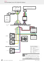
Page 23: ... are coloured Note When shortening the cable it is advisable to strip the insulation for an area of at least 5cm because the cable in the stripped insulation area is flexible this in turn ena bles the excess length required in the profile to be simply cleared away Table 1 Assignment of plug and socket connector X1 to the door to the spindle drive on cable harness 1 Contact Description Abbreviation...

Page 24: ...nal 1 AC IN1AC 9 Signal 2 IN2 Blue 10 Signal 3 IN3 11 Supply voltage 12V Red 12 Ground GND Black Connect cable using screwdriver 2 5x0 4mm To jam the plug and socket connector in place insert a screwdriver at an incline onto the outer visible spring in the terminal strip The screwdriver opens the spring contact and sticks there in place it can then be released Insert the wire and remove the screwd...

Page 25: ...he door drive electronics to the door frame Caution The opening for programming the control system must be down Note When installing the door precautions have to be taken to ensure that any unintended open ing over and beyond the maximum opening angle is avoided risk of damage to the swing door drive The maximum opening angle 105 must not be exceeded The specified position of the retaining bracket...

Page 26: ...n and close door Switch On the frame side Black box Access control system Finger scan Bluetooth PIN code keyboard White JST plug and socket connector Green Plug and socket connector Control unit Power supply unit for Roto E Tec DoorDrive IN 100 240V AC OUT 13V DC 120W Eneo power supply unit IN 100 240V AC OUT 24V DC 2 5A Two way intercom system Signal e g 12V Potential free contact Pink White Red ...

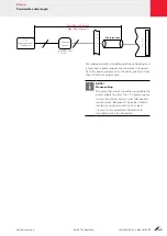
Page 27: ...ding with door blocking and a high load a power supply line resistance is required from the power supply unit to the cable junction of less than 0 3Ω for an output wire Note House wiring To ensure that correct operation is possible the power supply line from the 13 V power supply unit for the control system must fulfil specific requirements Because of the power transfer involved a wire cross secti...

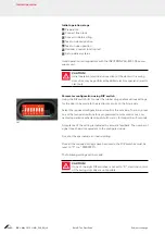
Page 28: ... DIP switch Ill 1 under the rubber plug enables various settings for the door to be made to the electronic circuits on the hinge side Select the required configuration and confirm the set value To do so press one of the two push buttons for a programmed remote control or a con nected operation mechanism push button etc for longer than 5 seconds Acceptance of the setting is indicated by acoustic fe...

Page 29: ...ics Select DIP switches 1 4 in required top group Change DIP switches 5 8 function for top group 0 OFF 1 ON Illustration of power supply unit with connection terminals Prepare power supply unit Status switched off Connect the red wire of the cable harness to the positive output Connect the black wire to the negative output Note To be conducted by electrics specialist electrician only The default p...

Page 30: ...peration mechanism for 5seconds until acoustic feedback is issued indicating the action was successful Note Use hand to keep door closed until the acoustic feedback is heard ON 1 2 3 4 5 6 7 8 5 Teaching in open position Manually open the door to gain access to the DIP switches Set the DIP switches to 1111 0010 move door to the required open position and hold it there Press an operation mechanism ...

Page 31: ...gle 1 Operating mode Setting operating mode on DIP switches 1 4 0000 DIP switch Description Feedback signal Personal setting 0 0 0 0 0 0 0 0 Normal operation Basic setting 1 1 1 1 Change to parameterisation mode Activate serial interface 2 Push to close Push to open Push to close or Push to open can be set to suit requirements In this function several options can be defined for the parameter as se...

Page 32: ...ins open Authorised closing Door only closes when authorisation has been issued or it remains closed Actuation input E1 DIP switch Description Feedback signal Personal setting 0 0 10 0 0 0 0 Feedback on current setting 0 0 0 1 E1 not assigned 1 0 0 1 0 E1 direct actuation 2 0 0 1 1 E1 authorised actuation 3 0 1 0 0 E1 authorisation 4 0 1 0 1 E1 direct actuation 5 0 1 1 0 E1 direct closing 6 0 1 1 ...

Page 33: ...gnal for the programmable output is not routed out of the door DIP switch Description Feedback signal Personal setting 0 1 1 0 0 0 0 0 Feedback on current status 0 1 General setting Continuous signal as long as authorisation issued 1 1 0 General setting Continuous signal if not closed 2 1 1 General setting Precision setting at bottom 3 0 1 0 0 Feedback on current status 0 1 Signal when opening Non...

Page 34: ...e DIP switch set to 01110111 Roto setting Following authorisa tion the door has to be opened within a period of one minute Operation during authorisation does not extend the authorisation period but rather it cancels it If the door is to then be closed again authorisation has to be is sued once more to enable the door to be closed within the one minute pe riod DIP switch Description Feedback signa...

Page 35: ...g ON 2 0 1 0 0 Feedback on current status 0 1 Signal when opening None 1 1 0 Signal when opening During start of actua tion 2 1 1 Signal when opening As long as actuation issued 3 1 0 0 0 Feedback on current status 0 1 Signal when closing None 1 1 0 Signal when closing During start of actuation 2 1 1 Signal when closing During start of actuation 3 only effective for lock with feedback 7 Hold open ...

Page 36: ...sing and the reversing function is switched on it opens again somewhat and after a brief pause it tries to close again for a specified number of attempts If the reversing function is switched off the door stops at the position that it encountered the obstacle When opening the door comes to a standstill without any further attempt to open further The number of continuation attempts and the pause ti...

Page 37: ...ault memory 1 1 0 0 12 Display fault memory 0 1 13 Display fault memory 1 0 14 Display fault memory 1 1 Acknowledge delete all faults Fault codes for faults at position 1 14 Number of tones issued Fault 1 RAM fault 2 ROM fault 3 Hall fault 4 Undervoltage fault 5 Excess current fault 10 Fault memory overrun 11 Special functions Teach in of zero position usually this is the closed door position Teac...

Page 38: ...nent on hinge side of door sash which accom modates the control system for the Roto E Tec DoorDrive Encoding A text code is used in a secret translation Changeable code Code that changes constantly A code is valid once only Its use prevents any impermissible access through repetition of a previously used radio signal when opening a door Regular beeping 0 25s beep and 0 25s no beep 1 n 0 25s 0 25s ...

Page 39: ...y programming error was deter mined reprogram control system contact specialist company Errors The swing door drive complies with a high quality standard and all the nec essary technical regulations and specifications Internal safety circuits and external safety circuits managed by the swing door drive are monitored on a cyclical basis Situations may occur during operation of the Roto E Tec DoorDr...

Page 40: ...en position still open Door reverses without crushing instance Sluggishness in system Wind load wind gust Check whether an obstacle can be detected at the swing door drive and remove it foreign ob ject Check door settings If necessary contact specialist company Adapt crush guard setting using the DIP switch Noise Joints not greased or dusty Swing door drive damaged Door has sagged Grease again wit...

Page 41: ...earing Before performing any mechanical work on the swing door drive disconnect it from the power supply Secure door against moving e g with a door stopper Do not touch the closing edge when checking functions Keep children away from the working area Property damage through incorrect handling The electronic circuit must not come into contact with water Do not open door sash any further than 105 Ge...

Page 42: ...lose smoothly Remove any coarse soiling Clean door latch using clean cloth If necessary also lubricate door latch 2 2 1 Visually inspecting electronic circuits The electronic circuits are installed in the door leaf No soiling or moisture in the electronic circuits Clean electronic circuits on outside using clean cloth If sealing plug 1 is damaged or missing replace it Re tighten 2 screws on cover ...

Page 43: ...thout any power supply Disconnect swing door drive from mains supply switch off circuit breaker Open door sash all way to end stop and then close again Switch on circuit breaker again When next actuated the door closes irrespective of the current position Have faulty behaviour checked and rectified by qualified personnel Checking maximum opening angle The maximum opening angle for automatic openin...

Page 44: ... cloth Apply one drop of resin free oil e g Molykote Omnigliss to moving parts Lubricating door hinge Remove any old excess lubricant using a dry lint free cloth Apply a drop of oil to the door hinge e g Molykote Omnigliss Care Specialist company End users Keep the hardware free from deposits and soiling Never use aggressive acidic cleaning or scouring agents Only use mild pH neutral cleaning agen...

Page 45: ...ation e g ground floor basement garage etc Door and swing door drive type Turn Only sash door with automatic door drive 1 sash inward opening sash overlapping on one or both sides Door opening angle Max 105 Sash width Min 700 to 1200mm Sash height Min 1600 to 2350mm Door sash weight Max 120kg Automatic door system user group Private area Private area 1 and 2 family home Regular use for defined and...

Page 46: ...tomatic Turn Only sash doors Hazard point between adjacent closing edge and ceiling Hazard point between adjacent closing edge and opposite closing edge wall Hazard point between adjacent closing edge and floor Hazard point between primary closing edge and opposite closing edge Risk of impact Risk of impact Risk of crushing ...

Page 47: ...ual doors Generally the swing door drive manufacturer has no influ ence on such hazard points The risk of crushing in contrast to the situation on the lock side primary closing edge is not protected by the low energy opera tion When operating the door it should be ensured that people are not inadvertently crushed Risk of being pulled in between the sash and the flooring adjacent closing edge Safet...

Page 48: ...r step in passage area thresholds and platforms 20mm This must be taken into consideration during the planning phase Risk through weathering e g ice in front of door etc Protection against weather influences The door installation position is to be chosen to match the planning requirements e g through installation in the reveal protection through canopy not to be installed on weather side no heavy ...

Page 49: ...served and checked both before and after installation of the door The signatory opposite hereby confirms that the hazard points have been adequately secured and considered and that the auto matic door system can therefore be put into operation Address Place Date Signature of door system installer The operator hereby declares that the residual risks are known that he is familiar with the installati...

Page 50: ... packaging consist mainly of raw materials that can be recycled The Roto E Tec DoorDrive and the accessories should not be disposed of with domestic waste Make sure that the old device and any accessories are routed to an appropriate disposal process Ensure that legal national regulations are complied with here ...

Page 51: ......
Page 52: ...oto Equipment Additional technology for windows and doors Roto Sliding Hardware systems for large sliding windows and doors MS B N Issue date May 2013 Subject to change IMO_294_EN_v0 2013 Roto Frank AG Roto is a registered trademark Roto Frank AG Window and door technology Wilhelm Frank Platz 1 70771 Leinfelden Echterdingen Germany Telephone 49 711 7598 0 Telefax 49 711 7598 253 info roto frank co...

Reviews: