Subject to change.
Roto E-Tec DoorDrive
IMO_294_EN_v0
May 2013
29
Initial operation
1.
Preparation
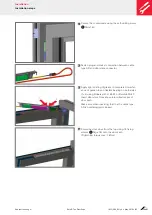
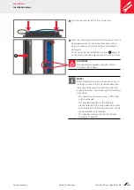
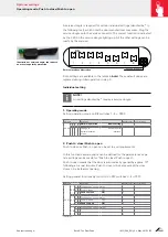
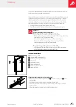
Remove the rubber plug of the elongated hole over the DIP switches
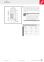
using a finger nail or a screwdriver. The DIP switches are now visible,
refer to illustration.
1
2
3
4
5
6
7
8
on
Illustration of DIP switch position
Control logics
Select DIP switches 1– 4 in required top group.
Change DIP switches 5–8 function for top group.
0 = OFF 1 = ON
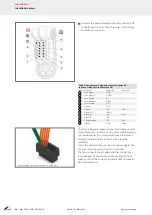
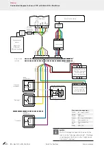
Illustration of power supply unit with
connection terminals
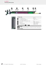
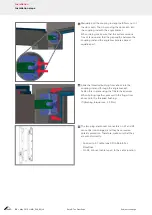
Prepare power supply unit (Status: switched off). Connect the red wire of
the cable harness to the positive output. Connect the black wire to the
negative output.
NOTE!
To be conducted by electrics specialist (electrician) only.
The default position for the DIP switch is OFF, this position has to be
adopted again following every action.
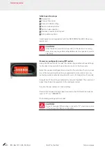
DIP switch
Service interface
Summary of Contents for E-Tec DoorDrive
Page 51: ......


