VLT
®
8000 AQUA
Programming
Thermistor
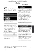
Is selected if a thermistor integrated in the
motor is to be able to stop the AFD in case of motor
overtemperature. The cut-out value is 3 kohm. If a
motor features a thermal switch instead, this can also
be connected to the input. If motors run in parallel,
the thermistors/thermal switches can be connected
in series (total resistance < 3 kohm). Parameter 117
Motor thermal protection
must be programmed for
Thermal warning
[1] or
Thermistor trip
[2], and the
thermistor must be inserted between terminal 53 or 54
(analoge voltage input) and termi-nal 50 (+10 V supply).
A motor thermistor connected to terminals 53/54
must be double isolated to obtain PELV.
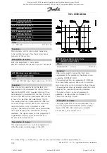
309 Terminal 53, min. scaling
(AI 53 SCALE LOW)
Value:
0.0 - 10.0 V
✭
0.0 V
Function:
This parameter is used for setting the signal value
that has to correspond to the minimum reference
or the minimum feedback, parameter 204
Minimum
reference, Ref
MIN
/413
Minimum feedback, FB
MIN
. See
Reference handling
or
Feedback handling
.
Description of choice:
Set the required voltage value.
For reasons of accuracy, voltage losses in long
signal lines can be compensated for.
If the time-out function is to be applied (parameters
317
Time out
and 318
Function after time out
),
the value must be set to > 1 V.
310 Terminal 53, max. scaling
(AI 53 SCALE HIGH)
Value:
0.0 - 10.0 V
✭
10.0 V
Function:
This parameter is used for setting the signal value that
has to correspond to the maximum reference value
or the maximum feedback, parameter 205
Maximum
reference, Ref
MAX
/414
Maximum feedback, FB
MAX
.
See
Reference handling
or
Feedback handling
.
Description of choice:
Set the required voltage value.
For reasons of accuracy, voltage losses in long
signal lines can be compensated for.
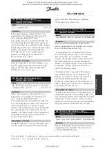
311 Terminal 54, analog input voltage
(AI [V] 54 FUNCT.)
Value:
See description of parameter 308.
✭
No operation
Function:
This parameter chooses between the different
functions available for the input, terminal 54.
Scaling of the input signal is done in parameter
312
Terminal 54, min. scaling
and in parameter
313
Terminal 54, max. scaling
.
Description of choice:
See description of parameter 308.
For reasons of accuracy, voltage losses in long
signal lines should be compensated for.
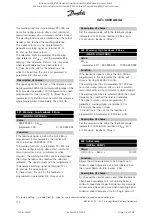
312 Terminal 54, min. scaling
(AI 54 SCALE LOW)
Value:
0.0 - 10.0 V
✭
0.0 V
Function:
This parameter is used for setting the signal value
that corresponds to the minimum reference value
or the minimum feedback, parameter 204
Minimum
reference, Ref
MIN
/413
Minimum feedback, FB
MIN
.
See
Reference handling
or
Feedback handling
.
✭
= factory setting. () = display text [] = value for use in communication via serial communication port
MG.80.A7.22 - VLT is a registered Danfoss trademark
117
Rosewood STP ST42 General (Operation and Maintenance Manual - Part 4:
Section 6.3 Manufacturers Manuals 6.3.33 Danfoss VLT Aquadrive 8000) Vendor Manual
QP Id: VM207
Active: 03/09/2013
Page 123 of 208

