VLT
®
8000 AQUA
Installation
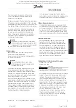
See
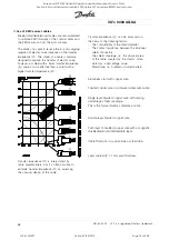
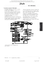
Earthing/Grounding of shielded (armoured control
cables
for correct termination of control cables.
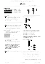
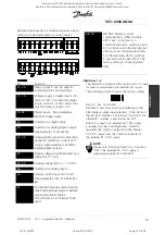
No.
Function
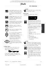
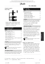
04, 05
Relay output 2 can be used for
indicating status and warnings.
12, 13
Voltage supply to digital inputs. For
the 24 V DC to be used for digital
inputs, switch 4 on the control card
must be closed, position "on".
16-33
Digital inputs. See parameters
300-307
Digital inputs
.
20
Common for digital inputs.
39
Common for analog/digital outputs.
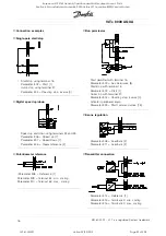
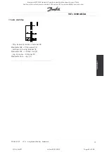
See
Examples of connection
.
42, 45
Analog/digital outputs for indicating
frequency, reference, current and
torque. See parameters 319-322
Analoge/digital outputs
.
50
Supply voltage to potentiometer and
thermistor 10 V DC.
53, 54
Analog voltage input, 0 - 10 V DC.
55
Common for analog inputs.
60
Analog current input 0/4-20 mA.
See parameters 314-316
Terminal
60
.
61
Termination of serial communication.
See
Earthing/Grounding of shielded
(armoured control cables
.
This terminal is not normally to be
used.
68, 69
RS 485 interface, serial
communication. When multiple
AFD
’
s are connected to a
communication bus, switches 2 and
3 on control card in the first and last
units must be closed (position ON).
For the remaining AFD
’
s, switches
2 and 3 must be open (OFF). The
factory setting is closed (position
ON).
■
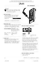
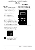
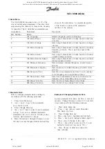
Switches 1-4
The dipswitch is located on the control card. It is used
for serial communication and external DC supply.
The switching position shown is the factory setting.
Switch 1 has no function.
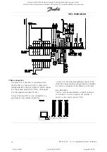
Switches 2 and 3 are used for terminating an RS
485 interface, serial communication. In the first and
the last AFD, switches 2 and 3 must be ON. In the
other AFD, switches 2 and 3 must be OFF.
Switch 4 is used if an external 24 V DC supply
is required for the control terminals. Switch 4
separates the common potential for the internal
24 V DC supply from the common potential of
the external 24 V DC supply.
NOTE
Please note that when Switch 4 is in position
"OFF", the external 24 V DC supply is
galvanically isolated from the AFD.
MG.80.A7.22 - VLT is a registered Danfoss trademark
73
Rosewood STP ST42 General (Operation and Maintenance Manual - Part 4:
Section 6.3 Manufacturers Manuals 6.3.33 Danfoss VLT Aquadrive 8000) Vendor Manual
QP Id: VM207
Active: 03/09/2013
Page 79 of 208

