background image

Chapter 5: Subsystem Maintenance 


Subsystem Maintenance 
 

5-21 


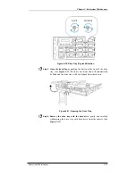
Figure 5-30: Drive Tray Key-lock Rotation 

Step 3.


Open the front flap

 by pushing the button at the front of the drive 

tray. (See 

Figure 5-31

) The drive tray front flap will automatically 

be lifted and the drive tray will be dislodged from the chassis.  


Figure 5-31: Opening the Front Flap 

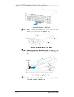
Step 4.


Remove the drive tray with the hard drive

, gently and carefully 

withdrawing the drive tray with hard drive from the chassis. (See


Figure 5-32

Summary of Contents for Galaxy A16F-R2422

Page 1: ...Galaxy Raid Model A16F R2422 FC 4G to SATA II RAID Subsystem Redundant Controller Installation and Hardware Reference Manual Version 0906 Version 1 0 08 2005...

Page 2: ...tion and Hardware Reference Manual ii Contact Information Americas Rorke Data Inc 9700 West 76th St Eden Prairie MN 55344 USA Tel 1 800 328 8147 Fax 1 952 829 0988 sales rorke com techsupport rorke co...

Page 3: ...of and specifically disclaims any implied warranties of merchantability or fitness for any particular purpose Furthermore Rorke Data reserves the right to revise this publication and to make changes f...

Page 4: ...ent is operated in a commercial environment This equipment generates uses and can radiate radio frequency energy and if not installed and used in accordance with the instruction manual may cause harmf...

Page 5: ...rd to establishing a satisfactory level of safety for persons using the device and for the area surrounding the apparatus This standard covers only safety aspects of the above apparatus it does not co...

Page 6: ...1 11 1 3 GALAXY MONITORING 1 12 1 3 1 I2C bus 1 12 1 3 2 LED Indicators 1 12 1 3 3 Firmware FW and RAIDWatch GUI 1 13 1 3 4 Audible Alarms 1 13 1 4 HOT SWAPPABLE COMPONENTS 1 13 1 4 1 Hot swap Capabi...

Page 7: ...ault Threshold Values 3 10 3 3 2 Failed Devices 3 11 3 4 I2C MONITORING 3 11 CHAPTER 4 SUBSYSTEM CONNECTION AND OPERATION 4 1 FC HOST CONNECTION PREREQUISITES 4 1 4 1 1 Choosing the Fibre Cables 4 1 4...

Page 8: ...5 14 5 7 1 Hard Drive Maintenance Overview 5 14 5 7 2 Replacing a Hard Drive 5 15 APPENDIX A UNINTERRUPTIBLE POWER SUPPLY A 1 UNINTERRUPTIBLE POWER SUPPLY OVERVIEW A 1 A 2 COMPATIBLE UPS SUPPLIES A 1...

Page 9: ...modules using the retention screws eject levers and the metal frames face plates Avoid touching PCB boards and connector pins To comply with safety emission or thermal requirements none of the covers...

Page 10: ...details about the hardware installation process Briefly describes how to monitor the subsystem Describes how to maintain the subsystem This manual does not Describe components that are not user servic...

Page 11: ...cts They can be read in any order Each statement is preceded by a round black dot Numbered Lists Numbered lists are used to describe sequential steps you should follow in order Important information t...

Page 12: ...t software or firmware updates Problems that occur during the updating process may cause unrecoverable errors and system down time Always consult technical personnel before proceeding with any firmwar...

Page 13: ...es failure at the same time when its configuration is RAID level 6 This generates a higher redundant level of data availability On this system the RAID level 6 and 60 are both ready for end users Plea...

Page 14: ...contents against the included Unpacking Checklist If any modules are missing please contact your subsystem vendor immediately 1 1 2 Enclosure Chassis 1 1 2 1 Chassis Overview The A16F R2422 RAID stora...

Page 15: ...he two 2 handles on the front of the subsystem enable you to easily insert extract the chassis into from a rack or cabinet The LCD panel on the left handle provides an easy way for you to monitor and...

Page 16: ...rear panel and is reserved for dual RAID controller modules two 2 standard BBUs two 2 host connection modules two 2 power supply units PSUs two 2 cooling modules and an enclosure configuration card T...

Page 17: ...rn the system on and off See Section 1 2 8 Cooling modules The redundant cooling modules provide ventilation to reduce the temperature within the subsystem See Section 1 2 9 Enclosure configuration ca...

Page 18: ...ller or different logical drive This will enable easier identification in a topology with numerous arrays 1 2 2 Drive Trays Figure 1 7 Drive Tray Front View PN GAL 9273A2DT2S1S The A16F R2422 subsyste...

Page 19: ...xteen 16 pre installed SATA II to SATA multiplexer MUX kits one in each drive tray These MUX kits facilitate the installation of separately purchased SATA II or SATA I drives When installing the drive...

Page 20: ...omes with two 2 pre set FC 4G host channels CH0 and CH1 The subsystem connects to the external FC 4G host computer s via eight 8 FC connectors which are located on the host connection modules These FC...

Page 21: ...nues the monitoring or configuration service Shielded cables must be used to protect against emissions Connect the other end of the Ethernet cable to a LAN hub port of the local network COM ports Each...

Page 22: ...is being changed the controller module must be removed from the subsystem chassis 1 2 7 Battery Backup Units BBUs Figure 1 11 BBU PN GAL 9273CBTC Two 2 standard Li ION battery backup units BBUs see F...

Page 23: ...12 each PSU comes with a single power socket for power cord plug in and a power switch on the right to turn the subsystem on and off Two 2 embedded cooling fans provide sufficient airflow to keep the...

Page 24: ...le operate with two rotation speeds Under normal operating conditions the cooling fans run at the low speed which is sufficient for maintaining efficient airflow across components Under the following...

Page 25: ...cations are listed in Appendix B 1 2 10 Enclosure Configuration Card Figure 1 14 DIP Switch A DIP switch on the enclosure configuration card see Figure 1 14 is conveniently located on the left side of...

Page 26: ...The bypass circuits ensure loop integrity and allow you to configure redundant paths to the host computers For configurations involving multi path multi host computers and cascading A16F R2422 be sur...

Page 27: ...connection of the existing host interface or Ethernet link to the array s LAN port 1 3 4 Audible Alarms The A16F R2422 subsystem comes with audible alarms that are triggered when certain active compon...

Page 28: ...es in dual active mode Host connection modules PSUs Cooling modules BBUs Hard drives NOTE Instructions on how to replace these hot swappable components are given in Chapter 5 1 4 3 Normalized Airflow...

Page 29: ...2 Installation Prerequisites 1 Static free installation environment The A16F R2422 subsystem must be installed in a static free environment to minimize the possibility of electrostatic discharge ESD...

Page 30: ...odule slot open will greatly affect the airflow efficiency within the enclosure and will consequently lead to system overheating Keep a faulty module in place until you have a replacement unit and you...

Page 31: ...in your body by wearing an anti static wristband Avoid carpets plastic vinyl and Styrofoam in your work area Handle all components by holding their edges or metal frames Avoid touching the exposed cir...

Page 32: ...r cords that came with the subsystem to connect the subsystem to the main power source Use the self purchased Fibre cable to connect a host port to the host computer or an external device 6 Power up O...

Page 33: ...level One 1 box contains the enclosure chassis with all the pre installed components The other two 2 boxes contain the power cords and accessory items Accessory items include an audio jack to DB9 Y ca...

Page 34: ...ot try to use drives of any other size Drive type The A16F R2422 described in this manual can use SATA II or SATA I hard drives Please ensure that you purchase the correct hard drives MUX kit All driv...

Page 35: ...he drive at an angle and inserting it into the drive tray See Figure 2 2 Figure 2 2 Installing a SATA Hard Drive Step 3 Connect the drive to the MUX kit by sliding it towards the rear of the drive tra...

Page 36: ...the unlocked position i e the groove on its face is in a horizontal orientation as shown in Figure 2 5 If the groove is in a vertical position then the key lock is locked and the front flap on the dri...

Page 37: ...n the MUX kit at the back of the drive tray is firmly connected to the corresponding connector on the backplane board If the front flap is not closed properly the connection between the hard drive and...

Page 38: ...ils are available for installing the subsystem into a rack or cabinet Please contact your system vendor for further details The subsystem should be installed in the rack or cabinet before the hard dri...

Page 39: ...tatus information can be obtained from the FW The FW is fully described in the Fibre to SATA RAID Subsystem Operation Manual that came with your system Please refer to this manual for further informat...

Page 40: ...of a number of threatening events occurs These events usually jeopardize the functional and operational integrity of the controller board and must be heeded at all times Events such as a breaching of...

Page 41: ...five 5 buttons three 3 LEDs and a 16x2 character LCD screen that indicates subsystem status Press the ENT button for two 2 seconds on the initial screen to enter the main menu Press the ESC button to...

Page 42: ...tus event has occurred OFF indicates that the subsystem and all its components are operating correctly Table 3 2 LCD Panel LED Definitions NOTE During the power up process the LCD panel ATTEN LED will...

Page 43: ...ctivity on the drive Power Status Green Red GREEN indicates that a drive is installed in the drive tray RED indicates that there is a drive failure Table 3 3 Drive Tray LED Definitions NOTE The contro...

Page 44: ...o activity on the drive ports 4 P_Fail Partner Fail Amber ON indicates that the partner controller in a redundant controller subsystem has failed 5 C_Dirty Cache Dirty Amber ON indicates that data is...

Page 45: ...s two 2 LEDs on the top The right LED is to indicate the status of each port see Figure 3 5 while the left LED is nonfunctional and will remind unlighted When the right LED illuminates static green me...

Page 46: ...le LED Color Status FLASHING Green The power supply has not been turned on The PSU module LED will blink when the subsystem is connected to a power source but not yet turned on Static Green The PSU is...

Page 47: ...ooling fans will return to low speed 3 3 Audible Alarm Different controller environmental and operational parameters like temperature etc have been assigned a range of values between which they can fl...

Page 48: ...alarm will sound Upper Threshold Lower Threshold 3 3V 3 6V 2 9V 5V 5 5V 4 5V 12V 13 2V 10 8V CPU Temperature 90 C 5 C Board Temperature 80 C 5 C Enclosure Ambient Temperature 40 C 0 C Table 3 7 Defau...

Page 49: ...ive a message that says Thermal Shutdown Enter Sleep Mode When the temperature falls back within normal range the battery will resume charging 3 4 I2 C Monitoring Presence detection and the general wo...

Page 50: ...Galaxy A16F R2422 Installation and Hardware Reference Manual Subsystem Monitoring 3 12 This page is intentionally left blank...

Page 51: ...both copper and optical connections Copper cable is cheaper but limited to lengths of less than 30m Optical cable can be used over longer distances and have been shown to be more reliable Due to the...

Page 52: ...ty features however they can still inflict damage 4 1 3 FC Speed Auto detection Speed auto detection is specified by the Fibre Channel standard If a 2Gb s or 1Gb s port is connected to a 4Gb s port it...

Page 53: ...r of hard drives that should be connected through the drive channels the transfer rates and the mechanical performance of the hard disks should be considered When cabling follow all the Fibre Channel...

Page 54: ...tware to be installed on the host computer 4 2 4 Redundant Controller Modes Two 2 different redundant controller modes are supported the active standby and the active active mode Active standby If thi...

Page 55: ...n Different logical groups of drives are mapped to the LUN numbers under a host ID For a multi host operation a logical drive configuration can be mapped to different ID LUN combinations In this case...

Page 56: ...ort names If a controller fails the surviving controller will avail itself using the failed controller s port names In the event of cable disconnection or RAID controller failure a valid data link thr...

Page 57: ...h 5 6 CH0 CH1 Auto 4G 2G 1G Speed Selection Speed auto detection is a specified feature of the Fibre Channel standard If one of the devices in the FC AL loop is set to an auto setting it will detect t...

Page 58: ...ices and or daisy chain other A16F R2422 subsystems The subsystem will automatically validate the dual loop configuration and the RAID controller will activate the enclosure monitoring service accordi...

Page 59: ...s can be created and made available separately through different ID LUN s on the host ports Configuration 1 Connect the left FC ports from each host connection modules to a dual ported host computer S...

Page 60: ...ters The dual path connection avoids single point of failure Multiple logical drives or multiple partitions can be created and made available separately through different ID LUN s on the host ports Th...

Page 61: ...k Configuration 1 The left FC ports of both host connection modules on the A16F R2422 are both connected to a two zone switch or two switches then to host computers The software that came with your sw...

Page 62: ...all of the components have been installed in the A16F R2422 and the host channels have been connected to the host the subsystem can be powered on 4 5 1 Check List BEFORE powering on the A16F R2422 pl...

Page 63: ...that have been connected to the A16F R2422 Please refer to the manual that came with your FC device to see the power on procedure Step 2 Power on the subsystems that are not connected directly to the...

Page 64: ...tire subsystem should be checked to ensure that everything is running smoothly and that there are no complications or malfunctions 1 Controller module LEDs The Controller Ready Host Busy and Drive Bus...

Page 65: ...ibre to SATA RAID Subsystem Operation Manual for more details NOTE The subsystem has been designed to run continuously If a component fails the fault can be corrected online 4 5 4 LCD Screen When powe...

Page 66: ...ound scrub are running Step 1 Stop I O access to the system Stop all I O access to the Galaxy subsystem Please refer to the related documentation of your applications Step 2 Flush the cache Locate the...

Page 67: ...ble WARNING Do not remove a failed component from the subsystem until you have a replacement on hand If you remove a failed component without replacing it the internal airflow will be disrupted and th...

Page 68: ...eadily at hand and can be quickly installed Removing subsystem components without a replacement can lead to permanent subsystem damage When replacing any hot swappable component caution should be take...

Page 69: ...e of the most sensitive components in the A16F R2422 All previously stipulated safety precautions see Section 2 3 must be strictly adhered to Failure to adhere to these precautions can result in perma...

Page 70: ...Module Screws Step 3 Remove the controller module by pressing down the two 2 levers at the back of the controller module The controller module will automatically be eased out of the controller module...

Page 71: ...ll the DIMM module onto the new controller module making sure that the memory module is securely in place See Section 5 3 Step 3 Install the controller module Make sure the levers at the back of the c...

Page 72: ...DR RAM DIMM module has been failed or a different size of DIMM module needs to be used the pre installed module must be removed and the new one installed Replacement and installation instructions are...

Page 73: ...e If the DIMM module is not firmly in place the subsystem will not run and the whole procedure must be repeated 5 3 2 DIMM Module Replacement Procedure NOTE If you are going to replace or upgrade a DI...

Page 74: ...security and helps minimize the loss of data during power shutdowns Each BBU consists of a bracket battery pack and a PCB board that connects to the backplane board The BBUs are pre installed into th...

Page 75: ...uiting can occur possibly causing functional defects acid leak and other hazardous results If a BBU leaks gives off a bad odor generates heat becomes discolored or deformed or in any way appears abnor...

Page 76: ...11 Fastening the BBU Retention Screws Step 4 Reset the subsystem for the new BBU to take effect The LED should start flashing to indicate that BBU is being charged When the BBU is fully charged the L...

Page 77: ...the chassis To replace a host connection module please follow these steps Step 1 Disconnect the SFP transceiver s that are connected to the host connection module Press the latch on the bottom of the...

Page 78: ...rew Step 3 Pull out the faulty host connection module and place it on a clean surface See Figure 5 15 Figure 5 15 Removing the Host Connection Module Step 4 Loosen four 4 screws on the host connection...

Page 79: ...ion Module NOTE A label sticker contents the host connection PCB board serial number is shipped in the host connection module spare part package You may stick it on the back of the metal bracket befor...

Page 80: ...installed with two 2 460W fully redundant hot swappable PSU modules These modules are located at the rear of the subsystem PSU bracket Each PSU module is permanently mounted in a two level steel brack...

Page 81: ...RNING Although the PSU modules are fully redundant it is not advisable to run the A16F R2422 with a single PSU module for an extended period of time If the second PSU module fails the subsystem will b...

Page 82: ...This will dislodge the PSU module from the subsystem Figure 5 23 Pressing Down the PSU Handle Step 5 Use the handle to gently pull the PSU module out of the enclosure See Figure 5 24 Figure 5 24 Disl...

Page 83: ...n handle is in its down position so that the saddle notches on the lower edges of the handle can lock on to the edge metal brackets along the chassis inner walls Push the PSU into the slot and pull th...

Page 84: ...y available that can be installed as soon as the failed cooling module has been removed WARNING The latches at the back of the cooling module secure the cooling module into the enclosure If these latc...

Page 85: ...latches will hold the module in place See Figure 5 28 Figure 5 28 Installing the New Cooling Module 5 8 Replacing a Failed Hard Drive 5 8 1 Hard Drive Maintenance Overview Hot swappable drive trays T...

Page 86: ...a replacement hard drive readily available before removing the failed drive from the subsystem Do not leave the drive tray slot open for an extended period of time or the normalized airflow will be di...

Page 87: ...utton at the front of the drive tray See Figure 5 31 The drive tray front flap will automatically be lifted and the drive tray will be dislodged from the chassis Figure 5 31 Opening the Front Flap Ste...

Page 88: ...es of the drive tray two on each side See Figure 5 33 Figure 5 33 Loosening the Hard Drive Screws Step 6 Remove the hard drive from the drive tray Disconnect the drive from the MUX kit and then remove...

Page 89: ...rews The MUX kit is secured on a drive tray by two 2 retention screws Turn the drive tray over and remove these screws See Figure 5 35 Figure 5 35 Removing the Retention Screws WARNING The MUX kits ar...

Page 90: ...over Insert the two 2 retention screws from the bottom of the drive tray These screws will firmly secure the MUX kit to the drive tray and facilitate the installation of the appropriate drive See Fig...

Page 91: ...ude Operating 12 000 ft Packaged 20 000 ft Power Requirements Input Voltage 100VAC 10A 240VAC 5A with PFC auto switching Frequency 47 63Hz Power Consumption 460W Dimensions Without Front Handles With...

Page 92: ...MI Shock Half sine Operating 10G peak 11ms duration Non operating 100G 180 in sec 240G 2ms half sine Square 240G 2ms half sine Vibration Operating 5 to 500Hz 0 2G X Y Z Non operating 5 to 500Hz 1 0G X...

Page 93: ...to 16 channels of 3 0Gbps SATA II Drive Channels All drive channels are pre configured and cannot be changed Cache Mode Write through write back adaptive write policy Cache Memory Pre installed 256MB...

Page 94: ...sive ambient temperature Cooling Fans Two fans for each unit inside PSU Temperature Operating 0 C to 50 C 32 F to 122 F Storage 40 C to 70 C 40 F to 158 F Humidity Operating 20 to 90 non condensing No...

Page 95: ...l mode settings are stored on NVRAM Failure Indicator Via audible alarm LCD keypad panel RAIDWatch Manager session event notifications or event prompts on terminal emulation A 7 Fault Tolerance Manage...

Page 96: ...Galaxy A16F R2422 Installation and Hardware Reference Manual A 6 Specifications This page is intentionally left blank...

Page 97: ...pe III bezel and Type II LED light pipe 2 to 1 SATA SATA I MUX conversion dual controller subsystems GAL 9273A2DT2S1S Drive tray Type III bezel and Type II LED light pipe 2 to 1 SATA SATA II MUX conve...

Page 98: ...9 GAL 9270CUPSYCab UPS Y cable audio jack to DB 9 GAL 9270CSFP2GA01 Agilent Fibre Channel 2 125 1 0625 GBd Small Form Pluggable Optical Transceiver LC waive length 850nm multi mode GAL 9270CFCCab01 O...

Page 99: ...a 20 pin host connector These port sockets receive Small Form Factor SFP fiber optic and copper based transceivers You may contact our technical support for an updated list of SFP transceiver modules...

Page 100: ...gnal logic 0 indicates normal operation 9 VEER Receiver ground common with transmitter ground 10 VEER Receiver ground common with transmitter ground 11 VEER Receiver ground common with transmitter gro...

Page 101: ...ller module rear panel for terminal emulation management PN GAL 9270ASCab Figure C 2 RS 232C Audio Jack Pin Outs CN1 Pin Number Pin Name 1 Ground 2 TXD 3 RXD CN2 Pin Number Pin Name 1 NC 2 RXD 3 TXD 4...

Page 102: ...on dual controller module rear panels for maintenance free terminal emulation management during controller failover failback GAL 9270AYCab Figure C 3 RS 232C Audio Jack Pin Outs CN1 Pin Number Pin Nam...

Page 103: ...is cable to connect the COM2 serial port to a UPS PN GAL 9270CUPSCab Figure C 4 RS 232C Audio Jack Pin Outs CN1 Pin Number Pin Name 1 Ground 2 TXD 3 RXD CN2 Pin Number Pin Name 1 TXD 2 RXD 3 NA 4 NA 5...

Page 104: ...Cable Pin Outs Use this cable to connect the COM2 serial port to a UPS PN GAL 9CAB000149G0 Figure C 5 RS 232C Audio Jack Pin Outs CN1 Pin Number Pin Name 1 Ground 2 TXD 3 RXD CN2 Pin Number Pin Name 1...

Page 105: ...l Modem A null modem is used for wire swap and is necessary for connecting COM1 CN2 to a PC serial port PN GAL 9011 Figure C 5 Null Modem Pin Outs Swap pin 2 and pin 3 Swap pin 4 and pin 6 Swap pin 7...

Page 106: ...e Reference Manual C 8 Pin Outs C 7 Ethernet Port Pin Outs Figure C 6 LAN Port Pin Outs Pin Pin Name Pin Pin Name 1 LAN_TXP 5 N2 2 LAN_TXN 6 LAN_RXN 3 LAN_RXP 7 N1 4 N2 8 N1 Table C 7 Ethernet Port Pi...

Page 107: ...Galaxy subsystem D 3 Serial Communication Cable Part Number GAL 9270CUPSCab 0030 GAL 9270CUPSYCab 0030 The A16F R2422 is shipped with a customized audio jack to DB9 serial communication Y cable that...

Page 108: ...efault baud rate for the COM 2 serial port is 38400 and must be changed to 2400 For instructions on changing the baud rate please refer to the Generic Operation Manual that came with the subsystem D 4...

Page 109: ...subsystem after the subsystem has been powered on but you will have to trigger the firmware to allow the subsystem to detect the UPS If daisy chain function is applied be sure the make all the cable...

Page 110: ...y and the UPS has either been disconnected from the AC power supply or the AC power supply has been disrupted The write policy will be changed from the default write back to write through If this mess...

Page 111: ...Level BPL Write Policy Status UPS connection is absent N A N A Write back UPS connection detected N A N A Write back Warning UPS AC Power Loss detected Disconnected BPL 50 Write through Warning UPS Ba...

Page 112: ...Galaxy A16F R2422 Installation and Hardware Reference Manual Uninterruptible Power Supply D 6 This page is intentionally left blank...

Reviews: