


Galaxy A16F-R2422 Installation and Hardware Reference Manual
Subsystem Maintenance
5-14
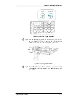
Step 7.
Fasten the retention screws
on the host connection module rear
panel to secure the module to the chassis. (See
Figure 5-19
)
Figure 5-19: Fasten the retention screws
Step 8.
Re-insert the SFP transceiver(s) that were previously removed.
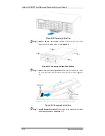
5.6 Replacing a Faulty PSU Module
5.6.1 PSU Module Overview
•
Two (2) redundant PSU modules:
The A16F-R2422 is preinstalled
with two (2) 460W, fully redundant, hot-swappable PSU modules.
These modules are located at the rear of the subsystem.
•
PSU bracket:
Each PSU module is permanently mounted in a two-level
steel bracket, creating a single unit. The PSU is located in the upper
level and a removable cooling module is mounted in the lower level.
When removing the PSU from the subsystem, the cooling module is
also being removed.
•
PSU printing mark:
Before you insert a new PSU, be sure that it has
the same printing mark on its handle as that shown on the handle of a
remaining PSU. Double-check to avoid mixing a PSU of previous
Galaxy series. (See
Figure 5-20
)


