Galaxy A16F-R2422 Installation and Hardware Reference Manual
Subsystem Connection and Operation
4-14
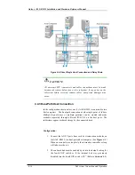
Figure 4-7: Power Sockets and Power Switches
CAUTION!
Although the PSUs are redundant and a single PSU can provide
sufficient power to the system, it is advisable to turn both the power
switches on. If only one (1) PSU is operating and that PSU fails, the
whole system will crash.
Step 4.
Power on the host computers.
The host computers should be the last devices that are turned on.
Please refer to the manual that came with your host computers to see
their own power on procedures.
4.5.3 Power On Status Check
Once the A16F-R2422 has been powered on, the status of the entire
subsystem should be checked to ensure that everything is running smoothly
and that there are no complications or malfunctions.
1.
Controller module LEDs:
The Controller Ready, Host Busy, and Drive
Busy LEDs should all flash green.
2.
Drive tray LEDs:
The green LEDs for all the drive trays that contain
hard drives should light up showing that there is power.
3.
LCD panel LEDs:
The blue LED on the LCD panel should illuminate,
indicating that power is being supplied to the system.
4.
Host connection module LEDs:
The right LED above each FC port
should illuminate green, indicating that the FC-AL loop has been
established.
5.
BBU LEDs:
The LEDs on the BBU rear panel should start flashing
amber, indicating that the BBU is being charged.
6.
PSU LEDs:
If the PSU is operating normally and experiencing no
problem after power on, the LEDs on the PSU should light green
constantly.


